Do you have a question about the Samsung AM080xXV Series and is the answer not in the manual?
| Power Supply | 220-240V, 50Hz |
|---|---|
| Refrigerant | R410A |
| Cooling Capacity (BTU) | 8, 000 BTU |
| Airflow (CFM) | 280 CFM |
| Noise Level (dB(A)) | 52 dB(A) |
| Cooling Capacity | 8000 BTU |
| Noise Level | 52 dB |
| Air Flow | 280 CFM |
| Weight | 9 kg |
Guidelines for safe and correct service procedures, including electrical parts and harness repair.
Handling PCB power terminals carefully and ensuring safety during electrical repairs.
Safety measures for handling refrigerants and welding air conditioner pipes.
General safety instructions for installation and maintenance, including pipe leakage and compressor handling.
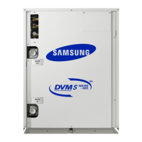
Details on Dual SSC System Technology, Dual Smart Inverter System, and Inverter circuit refrigerant cooling.
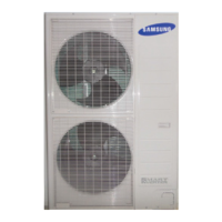
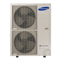
Comprehensive specifications for various outdoor unit models, including capacity, power, and dimensions.
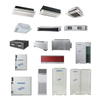
List of accessories and their specifications, such as Y-Joints, Distribution Headers, MCUs, and EEV Kits.
List of essential tools required for disassembly and reassembly procedures.
Step-by-step instructions for disassembling various outdoor unit models.
Detailed steps and precautions for safely exchanging the compressor.
Instructions for disassembling and handling MCU and EEV Kit components.
Explanation of the outdoor unit display functions and error codes.
Guide to entering and using various service operation modes for troubleshooting.
Reference tables for EEPROM codes and error display interpretation.
Detailed troubleshooting steps for various error codes and symptoms.
Diagram and pin assignments for the main PCB assembly.
Diagram and pin assignments for the main-hub PCB assembly.
Diagram and pin assignments for the inverter PCB assembly.
Diagram and pin assignments for the fan PCB assembly.
Diagram and pin assignments for the EMI PCB assembly.
Diagram and pin assignments for the sub-comm PCB assembly.
Comprehensive wiring diagram for multiple outdoor unit models.
Specific wiring diagram for AM080/100/120/200FXWA outdoor units.
Wiring diagram for larger capacity and specific model series.
Specific wiring diagram for the AM080JXVAFH model.
Specific wiring diagram for the AM100/120JXVAFH models.
Specific wiring diagram for the AM140/160/180/200JXVAFH models.
Specific wiring diagram for the AM080-220JXVAJH models.
Refrigerant cycle diagrams for specific outdoor unit models.
Refrigerant cycle diagrams for specific outdoor unit models.
Refrigerant cycle diagrams for specific outdoor unit models.
Refrigerant cycle diagrams for AM080/100/120FXWA and AM200FXWA models.
Refrigerant cycle diagrams for various high-capacity outdoor units.
Refrigerant cycle diagrams for specific outdoor unit models.
Refrigerant flow diagrams for cooling and heating operations.
Explanation of the function of various components in the refrigerant cycle.
Guide to setting the outdoor unit's DIP switches for various functions.
Instructions for setting outdoor unit functions using tact switches.
Steps for performing Auto Trial Operation and its preliminary checks.
Procedure for automatically checking the refrigerant amount.
Explanation of the model naming structure and its components.