18 S&C Instruction Sheet 719-501
Inspection and Maintenance
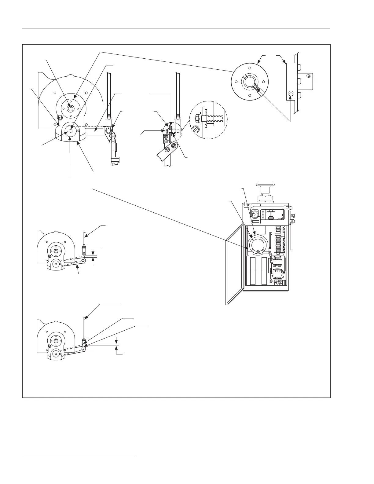
Figure 8� Brake inspection procedure�
Motor shaft square key
Brake
disc
-inch socket-
head recess for
adjusting pad
assembly
Pad
assembly
Caliper assembly
Pad assembly socket-
head set screw
(-inch Allen wrench
required)
Brake
lever
Angle
bracket
–20 x 1¼-inch
hex-head screw
Spacer bushing
Hub
¼–20-inch socket-head set screw
(⅛-inch Allen wrench required)
DETAIL A
Brake Assembly
DETAIL C
Location of Motor Shaft Set Screw (115
& 230 Vac Operator Only)
–18 x 1¼-inch
screws
Motor
Operating linkage
disconnected from
brake lever
Brake lever
⅝-inch (16 mm) to ¾-inch
(19 mm) vertical free play
DETAIL B
Measuring Brake Lever Free Play
Operating linkage
connected to brake lever
Point of initial manual brake release
Brake lever
at bottom of its stroke (manual operating handle
in cranking position)
⅛
-inch (3-mm) to
¼
-inch (6-mm) travel
DETAIL D
Measuring Brake Lever Stroke
 Loading...


