17
Cross-Sectional (A)+(B) (A) Power Supply Wiring Length (ft) (C) Control
Fuse or Circuit
Area (AWG)
(B) Power Line Length (ft) Line Length (ft)
Model (#14) (#12) (#14)
Breaker Capacity
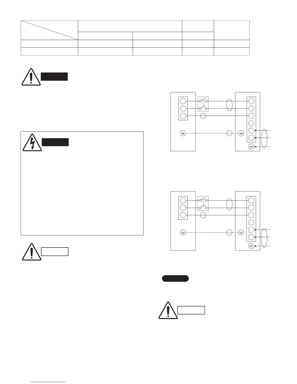
C1271, CL1271 131 (Max.) 230 (Max.) 65 (Max.) 20A
C1872, CL1872 131 (Max.) 230 (Max.) 98 (Max.) 20A
# ... AWG (American Wire Gauge)
Table 4
G Be sure to comply with local codes on running the
wire from the indoor unit to the outdoor unit (size
of wire and wiring method, etc.).
G Each wire must be firmly connected.
G No wire should be allowed to touch refrigerant
tubing, the compressor, or any moving part.
G Be sure to connect the power supply line to the
outdoor unit as shown in the wiring diagram. The
indoor unit draws its power from the outdoor unit.
G Do not run wiring for antenna, signal, or power
lines of television, radio, stereo, telephone, secu-
rity system, or intercom any closer than 3'3" (1 m)
from the power cable and wires between the
indoor and outdoor units. Electrical noise may
affect the operation.
G To avoid the risk of electric shock, each air con-
ditioner unit must be grounded.
G For the installation of a grounding device,
please observe local electrical codes.
G Grounding is necessary, especially for units
using inverter circuits, in order to release
charged electricity and electrical noise caused
by high tension.
Otherwise, electrical shock may occur.
G Place a dedicated ground more than 7' (2 m)
away from other grounds and do not have it
shared with other electric appliances.
*
A disconnect switch may be required by
national or local codes.
NOTE
Always comply with national and local code
requirements.
Fig. 7a
(C1271, CL1271)
Disconnect
switch
*
1
2
3
1
2
3
4
5
6
Grounding line
115V
115V
115V
INDOOR
UNIT
OUTDOOR
UNIT
Field supply
Grounding
line
L
N
Power supply
Single phase 115V 60HZ
Ter m inal Terminal
(A)
(B)
(C)
(B)
Fig. 7b
(C1872, CL1872)
Disconnect
switch
*
1
2
3
1
2
3
4
5
6
Grounding line
230/208V
230/208V
230/208V
INDOOR
UNIT
OUTDOOR
UNIT
Field supply
Grounding
line
L
1
L
2
Power supply
Single phase 230/208V 60HZ
Ter m inal Terminal
(A)
(B)
(C)
(B)
WIRING SYSTEM DIAGRAM
08-221 XS1271 9/12/08 2:52 PM Page 17
 Loading...