Index
1. Safety instructions..................................................................................................................................................................................................1
2. WARNING.............................................................................................................................................................................................................1
3. Precaution against X-Rays.....................................................................................................................................................................................1
4. Technical characteristics........................................................................................................................................................................................2
5. Safety .....................................................................................................................................................................................................................2
6. EMC (Electromagnetic Compatibility).....................................................................................................................................................................2
7. Factory special mode..............................................................................................................................................................................................3
8. “HOTEL” and “RENTAL” modes............................................................................................................................................................................3
9. Automatic channel search reactivating...................................................................................................................................................................3
10. Block diagram.......................................................................................................................................................................................................4
11. Power supply........................................................................................................................................................................................................5
12. Microprocessor and Teletext ................................................................................................................................................................................5
13. Video processor/Comb filter.................................................................................................................................................................................5
13.1 Video Intermediate Frequency Section ..........................................................................................................................................................5
13.2 Horizontal and vertical synchronisation..........................................................................................................................................................5
13.3 Geometry.......................................................................................................................................................................................................6
13.4 Filters and video switches..............................................................................................................................................................................6
13.5 Colour decoder ..............................................................................................................................................................................................6
13.6 RGB Processing............................................................................................................................................................................................6
13.7 RGB Control..................................................................................................................................................................................................7
13.8 Supply and bandgap decoupling....................................................................................................................................................................7
14. Audio processor/A3D Surround/Output amplifiers/Sound IF................................................................................................................................7
15. Service menu........................................................................................................................................................................................................8
16. Adjustment and repair procedures .....................................................................................................................................................................10
16.1 Notes about the adjustment:........................................................................................................................................................................10
16.2 Switch-on sequence. ...................................................................................................................................................................................11
16.3 Protect modes and failure indication............................................................................................................................................................11
16.4 Protect mode inhibition ................................................................................................................................................................................11
16.5 Power supply repair procedure ....................................................................................................................................................................11
16.6 Non-volatile memory (NVM) replacement, IC125.........................................................................................................................................11
17. Failure location flow-charts.................................................................................................................................................................................12
18. Complete PCB codes for after sales service......................................................................................................................................................15
19. CHASSIS ELECTRICAL PARTS LIST CE21FN1-E / CE25FN1-E / CE28FN1-E ...........................................................................................16
20. CE21FN1-E CABINET PARTS LIST ................................................................................................................................................................17
21. CE25FN1-E CABINET PARTS LIST ................................................................................................................................................................18
22. CE28FN1-E CABINET PARTS LIST ................................................................................................................................................................19
23. Parts List............................................................................................................................................................................................................20
CE28FN1-E
CE25FN1-E
CE21FN1-E
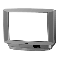
Service Manual
Models:
CRT 28” A59EAK071X11
CRT 25” A66EAK071X11
CRT 21” A51EAL155X10
CRT 21” A51EAL155X11
CHASSIS No 2103
EB5-A

 Loading...