1
S4179705
INSTALLATION INSTRUCTIONS
— Split System Heat Pump —
CONTENTS
IMPORTANT Page
Please Read Before Starting .................................. 2
1. GENERAL ............................................................. 3
1-1. Tools Required for Installation (not supplied)
1-2. Accessories Supplied with Unit
1-3. Optional Copper Tubing Kit
1-4. Type of Copper Tube and Insulation Material
1-5. Additional Materials Required for Installation
1-6. Operating Range
1-7. Tubing Length
2. SELECTING THE INSTALLATION SITE ............ 7
Indoor Unit
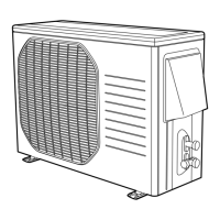
Outdoor Unit
2-1. Air Discharge Chamber for Top Discharge
2-2. Installing the Unit in Heavy Snow Areas
2-3. Precausions when installing in Heavy Snow
Areas
2-4. Dimensions of Snow / Wind-proof Ducting
and Refrigerat Tubing Space for Installtion
3. HOW TO INSTALL THE INDOOR UNIT ............ 11
■ Recessed Type (XHS Type) ............................. 11
3-1. Suspending the Indoor Unit
3-2. Preparation for Suspending
3-3. Placing the Unit Inside the Ceiling
3-4. Installing the Drain Piping
3-5. Checking the Drainage
3-6. Before Installing the Ceiling Panel
3-7. Installing the Ceiling Panel
3-8. When Removing the Ceiling Panel for
Servicing
3-9. Duct for Fresh Air
■ Ceiling-Mounted Type (THS Type) .................. 19
3-10. Suspending the Indoor Unit
3-11. Duct for Fresh Air
3-12. Installing the Drain Piping
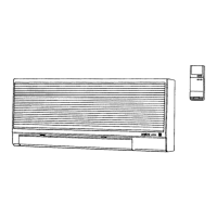
■ Wall-Mounted Type (KHS Type) ..................... 23
3-13. Removing the Wall Fixture from the Unit
3-14. Selecting and Making a Hole
3-15. Installing the Wall Fixture onto Wooden or
Gypsum Wall
3-16.
Removing the Casing to Install the Indoor Unit
3-17. Preparing the Indoor Side Tubing
3-18. Wiring Instructions
3-19. Wiring Instructions for Inter-Unit Connections
3-20. Shaping the Tubing
3-21. Installing the Drain Hose
4. HOW TO INSTALL THE REMOTE
CONTROL UNIT ................................................. 32
■ Wireless Remote Control Unit
4-1. Mounting on a Wall
85464179705002
Model Combinations
Combine indoor and outdoor units only as listed below.
Indoor units Outdoor units
XHS2432 (PNR-XHS2432) CH2432
THS2432
KHS2432
XHS3632 (PNR-XHS3632) CH3632
THS3632
KHS3632
Power Supply :
60Hz, single-phase, 208/230 V
5. ADDRESS SWITCHES .......................................33
5-1. Finding the Address Switches
5-2. Switch Positions for 2 Units or 2 Groups of
Units
5-3. Test Run Switch
6. HOW TO INSTALL THE OUTDOOR UNIT ........ 35
6-1. Removing the Protective Spacer for
Transportation
6-2. Installing the Outdoor Unit
6-3. Tubing Direction
7. ELECTRICAL WIRING .......................................36
7-1. General Precautions on Wiring
7-2. Recommended Wire Length and Wire
Diameter for Power Supply System
7-3. Wiring System Diagram
7-4. How to Connect Wiring to the Terminal
8. HOW TO PROCESS TUBING ........................... 38
8-1. Use of the Flaring Method
8-2. Flaring Procedure with a Flare Tool
8-3. Precaution before Connecting Tubes Tightly
8-4. Precautions during Brazing
8-5. Connecting Tubing between Indoor and
Outdoor Units
8-6. Insulating the Refrigerant Tubing
8-7. Taping the Tubes
8-8. Finishing the Installation
9. AIR PURGING ....................................................41
■ Air Purging with a Vacuum Pump
(for Test Run)
10.TEST RUN .......................................................... 44
10-1. Preparing for Test Run
10-2. Performing Test Run
10-3. Items to Check Prior to Test Run
10-4. PCB Setting
10-5. R.C. Address Setting
10-6. Misoperation Alarm Indicators
■ Basic Functions of the Service Valves
■ Pump Down
Units should be installed by licensed contractor
according to local code requirements
SANYO FISHER COMPANY
A DIVISION OF SANYO NORTH
AMERICA CORPORATION
21605 Plummer Street
Chatsworth, CA91311