First edition: Mar 2014 Q04501900
©2014 SATO CORPORATION
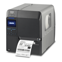
UHF RFID Configuration Guide
Thank you for choosing a SATO RFID Printer. This guide will help configure the printer to encode your inlays.
Refer to the CL4NX Operator Manual for more information.
You can access the CL4NX Operator Manual from the website for your region linked from
www.satoworldwide.com.
1 Examine labels.
Refer to the attached CL4NX UHF Inlay Configuration Guide for what measurements you should take and
what they mean, as well as a list of inlays and their required configurations.
2 Set up printer.
A) Menu Settings:
Adjust the Antenna Pitch, Write Power and Read Power according to required levels on attached list.
1. Turn on Power 2. Printer Comes Online 3. Switch to Offline
(Line button on the Operator
Panel)
4. Enter Menu
(Right Arrow button on the Opera-
tor Panel)
5. Select “Interface” 6. Select “RFID”
Four Easy Steps of RFID Configuration
1 Examine Labels to determine printer
settings.
2 Set up printer.
A) Menu Settings
B) Physical Antenna Position
3 Set Labels and Carbon Ribbon.
4 Confirm operation by printing/encoding a
label.
• Explanation of RFID menu items
* BOLD items
are default settings.
Antenna Pitch Allows the user to select the “Standard” or “Short” pitch antenna set-
tings. See under “Antenna Pitch” in the CL4NX UHF Inlay Placement
& Configuration Table.
Write Power Radio Power level used to write information to RFID tag. “0 - 10 - 24”
(dBm) See under “Write” under “Power” in the CL4NX UHF Inlay
Placement & Configuration Table.
Read Power Radio Power level used to read information from RFID tag. “0 - 10 -
24” (dBm) See under “Read” under “Power” in the CL4NX UHF Inlay
Placement & Configuration Table.
Tag Offset Distance to print on label BEFORE pausing to encode RFID. “0 - 240”
(mm in unit) This setting will be used when labels aren’t compatible
with the CL4NX’s antenna positions. For more information about com-
patible antenna positions, refer to the attached CL4NX UHF Inlay
Placement and Configuration Table.
Reader Model Display model of installed RFID reader module.
Reader Version Display firmware version of installed RFID reader module.
View When selected printer will attempt to read the tag currently set in the
printer.
Select the memory bank from which to read information. “EPC”, “TID”,
“User”, “PC”
Retry Mode Determine whether to retry encoding of failed data after error recovery.
“Retry”, “Release”
The Release option deletes the current print job, allowing the printer to
move on to the next print job. When Retry is selected, the printer will
continue to attempt encoding the same data.
Retries Number of failed encoding attempts before error warning/print pause.
“0 - 1 - 9”
Mark bad tags Mark bad tags with slash marks. “Enable”, “Disable”
Log RFID Data Record encoded tag information. “Disable”, “Enable”
Data To Record Used with Log mode: determine what information to record. “EPC and
TID”, “EPC”, “TID”
Output Error Mode Allows the user to set the signal type for RFID errors. “Pulse”, “Level”
Pulse Length Allows the user to select the length of an RFID error pulse.
This menu is displayed when the Output Error Mode is set in Pulse.
“100ms”, “200ms”, “300ms”, “400ms”, “500ms”
Counters
Life time Life time counter displays the number of encoding successes, failures,
and total attempts. (Count Success, Count Failure, Count Total)
User User counter displays the number of encoding successes, failures,
and total attempts. (Count Success, Count Failure, Count Total, Clear
Counter)
CL4NX_RFID.fm Page 39 Monday, March 10, 2014 7:26 PM