www.scheppach.com
GB
|
43
11. Use one M8 x 78 mm coach bolt (A), one spacer
(J) and one M8 nut (K) on each side to connect the
machine stand part 3 (25c) to the machine stand
part 6 (25f).
NOTE: Do not over-tighten the screws. The parts
must be able to move freely.
12. Use one M8 x 78mm coach bolt (A), one spacer
(J) and one M8 nut (K) on each side to connect the
machine stand part 4 (25d) to the machine stand
part 3 (25c).
13. Now use the wheel screws (P) to connect the two
wheels (13) to the machine stand part 4 (25d) as
14. Turn the machine so that it rests on the machine
stand (24).
15. Release the locking latch (14) and fold up the ma-
chine stand until the locking pin engages into the
locking latch (14).
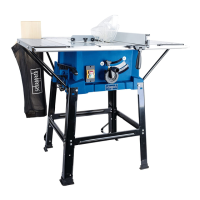
9.2 Removing the table inlay (g. 16)
1. Set the saw blade (1) to the max. cutting depth,
move to the 0° position and lock in place (see 11.2).
2.
turn anti-clockwise.
3. Remove the table inlay (4) from the saw table (5).
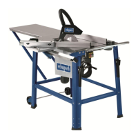
9.3 Riving knife
m WARNING
Danger of injury due to unexpected start-up of the ma-
chine
- Remove the mains plug from the socket.
You need to remove the table inlay (4) before you can
install and adjust the riving knife (3).
9.3.1 Insert and adjust the riving knife (g. 17 + 18)
1.
2. Push the riving knife (3) into the bracket.
NOTE: This step can be omitted if the riving knife
(3) has already been inserted.
3. Align the riving knife (3) so that
a) The distance between the saw blade (1) and the
b) The saw blade (1) is parallel to the riving knife
(3).
3.
NOTE:
• If connections are secured with a screw (round-head
or hexagon), hexagon nuts and washers, the washer
• Insert screws each from outside to inside. Secure
connections with nuts on the inside.
• Tighten the nuts and screws during assembly only
If you tighten the nuts
-
sible to complete the assembly.
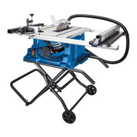
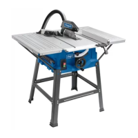
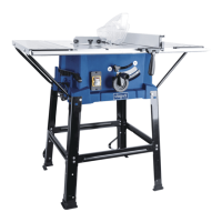
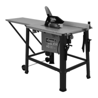
9.1 Fitting the machine stand (g. 5 - 15)
1. Turn the machine over and place it on a clean sur-
face.
2. Use two M6 x 53mm hexagon socket screws (B),
two large washers (I) and two M6 nuts (L) each to
attach the two machine stand parts 6 (25f) to the
machine housing.
3. Connect the two round end caps (O) to the ends of
the machine stand parts 6 (25f).
4.
(N) to the other ends of the machine stand parts
6 (25f).
5. Use two M5 x 50 mm Phillips screws (C) and two
M5 nuts (M) to connect the machine stand part 4
(25d) to the machine stand part 5 (25e).
6. Use two M8 x 78 mm coach bolts (A), two spacers
(J) and two M8 nuts (K) to connect the machine
stand part 4 (25d) to the machine stand part 1
(25a).
NOTE: Do not over-tighten the screws. The parts
must be able to move freely.
NOTE: Ensure that the locking handle (14) on the
machine stand part 4 (25d) is on the same side as
the locking pin on the machine stand part 1 (25a).
7.
the machine stand part 4 (25d).
8. Use two M8 x 78 mm coach bolts (A), two spacers
(J) and two M8 nuts (K) to connect the machine
stand part 4 (25d) to the machine stand part 6
(25f). (
NOTE: Do not over-tighten the screws. The parts
must be able to move freely.
NOTE: Ensure that the locking handle (14) is on
the same side as the ON/OFF switch (15).
9. Use two M5 x 40 mm Phillips screws (D) and two M5
nuts (M) each to connect the machine stand part 2
(25b) to the machine stand part 3 (25c).
10.
the machine stand part 3 (25c).
 Loading...