R-231F
12
TEST PROCEDURES
PROCEDURE
LETTER
COMPONENT TEST
2-1 Programming problems.
a) When touching the pads, a certain group of pads do not produce a signal.
b) When touching the pads, no pads produce a signal.
2-2 Display problems.
a) For a certain digit, all or some segments do not light up.
b) For a certain digit, brightness is low.
c) Only one indicator does not light up.
d) The corresponding segments of all digits do not light up; or they continue to light up.
e) Wrong figure appears.
f) A certain group of indicators do not light up.
g) The figure of all digits flicker.
2-3 Other possible problems caused by defective control unit.
a) Buzzer does not sound or continues to sound.
b) Clock does not operate properly.
c) Cooking is not possible.
N RELAY TEST
L KEY UNIT TEST
If the display fails to clear when the STOP/CLEAR pad is depressed, first verify the flat ribbon cable
is making good contact, verify that the 2nd. interlock relay control switch operates properly; that is the
contacts are closed when the door is closed and open when the door is open. If the 2nd. interlock relay
control switch is good, disconnect the flat ribbon cable that connects the key unit to the control unit
and make sure the 2nd. interlock relay control switch is closed (either close the door or short the 2nd.
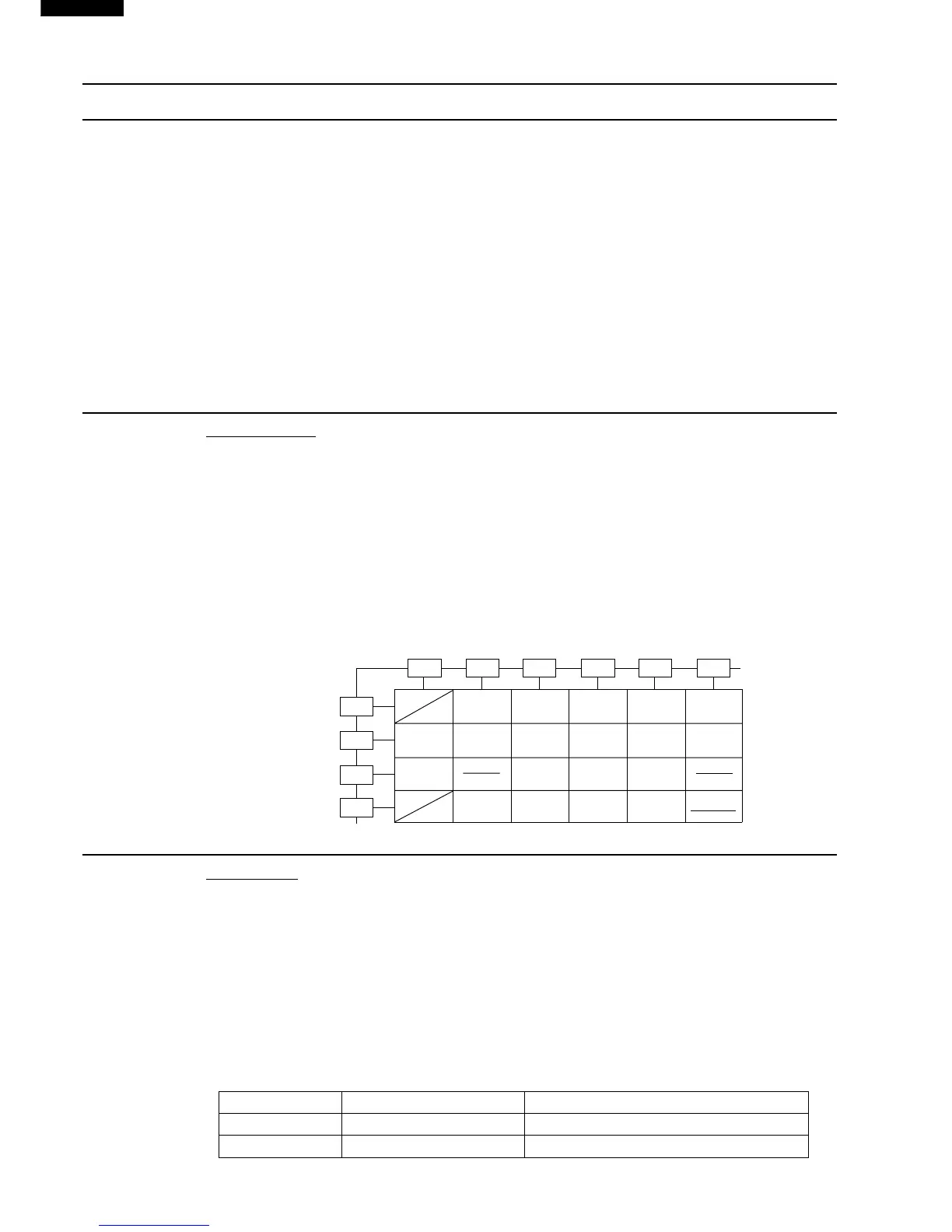
interlock relay control switch connecter). Use the Key unit matrix indicated on the control panel
schematic and place a jumper wire between the pins that correspond to the STOP/CLEAR pad
making momentary contact. If the control unit responds by clearing with a beep, the key unit is faulty
and must be replaced. If the control unit does not respond, it is faulty and must be replaced. If a specific
pad does not respond, the above method may be used (after clearing the control unit) to determine
if the control unit or key pad is at fault.
CARRY OUT 3D CHECKS.
Remove the outer case and check voltage between Pin No. 3 of the 2 pin connector (A) and normal
open terminal of the relay (RY2) on the control unit with an A.C. voltmeter.
The meter should indicate 230-240 volts, if not check oven circuit.
RY1 and RY2 Relay Test
These relays are operated by D.C. voltage
Check voltage at the relay coil with a D.C. voltmeter during the microwave cooking operation.
DC. voltage indicated .......... Defective relay.
DC. voltage not indicated .... Check diode which is connected to the relay coil. If diode is good,
control unit is defective.
RELAY SYMBOL OPERATIONAL VOLTAGE CONNECTED COMPONENTS
RY1 Approx. 14.0V D.C. Oven lamp / Turntable motor / Cooling fan motor
RY2 Approx. 12.5V D.C. Power transformer
CARRY OUT 4R CHECKS.
1
2
3
45
6
7
89
0
POWER
LEVEL
INSTANT
COOK
START
JACKET
POTATO
FROZEN
VEGETABLES
BEVERAGE
FRESH
VEGETABLES
TIMER
CLOCK
EASY
DEFROST
DINNER
PLATE
EXPRESS
DEFROST
RICE PASTA
G 1 G 2 G 3 G 4 G 5 G 6
G 7
G 8
G 9
G10
STOP
CLEAR
 Loading...