R-231F
19
3. Remove the three (3) screws holding the magnetron to
the waveguide.
4. Remove the magnetron from waveguide.
5. Now, the magnetron is free.
CAUTION: WHEN REPLACING THE MAGNETRON,
BE SURE THE R.F. GASKET IS IN PLACE
AND THE MAGNETRON MOUNTING
SCREWS ARE TIGHTENED SECURELY.
To remove the components, proceed as follows.
1. CARRY OUT
3D CHECKS.
2. Remove one (1) screw holding capacitor holder to rear
cabinet.
3. Disconnect the H.V. wire of the H.V. rectifier assembly
from the magnetron.
4. Disconnect the filament lead of the power transformer
from the H.V. capacitor.
5. Remove one (1) screw holding ground side terminal of
high voltage rectifier assembly, and remove capacitor
holder.
6. Disconnect all the leads and terminals of high voltage
HIGH VOLTAGE COMPONENTS REMOVAL
(HIGH VOLTAGE CAPACITOR AND HIGH VOLTAGE RECTIFIER ASSEMBLY)
rectifier assembly from high voltage capacitor.
7. Now the H.V. rectifier assembly and H.V. capacitor
should be free.
CAUTION: WHEN REPLACING HIGH VOLTAGE REC-
TIFIER ASSEMBLY, ENSURE THAT THE
CATHODE (GROUND) CONNECTION IS
SECURELY FIXED TO THE CAPACITOR
HOLDER WITH A GROUNDING SCREW.
CAUTION: DO NOT REPLACE ONLY HIGH VOLT-
AGE RECTIFIER. WHEN REPLACING IT,
REPLACE HIGH VOLTAGE RECTIFIER
ASSEMBLY.
1. CARRY OUT 3D CHECKS.
2. Disconnect the wire leads (main wire harness) from
power transformer.
3. Disconnect the lead from magnetron filament.
4. Disconnect the leads of the power transformer from
high voltage capacitor.
5. Remove the two (2) screws holding the transformer to
bottom plate from the upper side.
6. Remove the remaining two (2) screws from the bottom.
7. Remove the transformer.
8. Now the power transformer is free.
POWER TRANSFORMER REMOVAL
Re-install
1. Rest transformer on the bottom plate with its primary
terminals toward the oven face plate.
2. Secure transformer with four (4) screws to the bottom
plate.
3. Re-connect wire leads (primary and high voltage) and
filament leads to the power transformer, magnetron
and high voltage capacitor, referring to "Pictorial Dia-
gram".
4. Re-install outer case and check that the oven is oper-
ating properly.
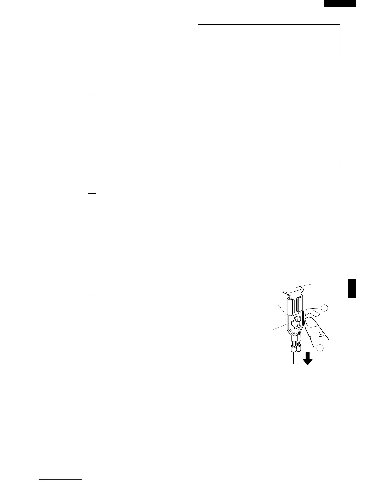
1. CARRY OUT 3D CHECKS.
2. Push the lever of positive lock
®
connector.
3. Pull down on the positive lock
®
connector.
CAUTION: WHEN CONNECTING THE POSITIVE
LOCK
®
CONNECTORS TO THE TERMI-
NALS, INSTALL THE POSITIVE LOCK
®
SO
THAT THE LEVER FACES YOU
POSITIVE LOCK
®
CONNECTOR (NO-CASE TYPE) REMOVAL
Figure C-1. Positive lock
®
connector
1. CARRY OUT 3D CHECKS.
2. Disconnect the leads from the control unit.
3. Remove the one (1) screw holding the control panel to
CONTROL PANEL ASSEMBLY REMOVAL
the front plate of the oven cavity.
4. Now, the control panel assembly is free.
Removal
1. Disconnect the oven from the power supply.
2. Remove the turntable and turntable support from the
oven cavity.
3. Turn the oven over.
TURNTABLE MOTOR REMOVAL
4. Remove the one (1) screw holding the turntable motor
cover to the bottom plate.
5. Now, the turntable motor cover is free.
6. Disconnect the wire leads from the turntable motor.
7. Remove the single (1) screw holding the turntable
 Loading...