R-231F
21
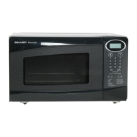
Power Supply
Cord
Oven Cavity
Back Plate
Square
Hole
Moulding
Cord Stopper
latch hook, pushing and pulling lower portion of the
door toward the oven face. Both results (play in the
door) should be less than 0.5mm.
2. The 1st. latch switch, 2nd. interlock relay control switch
interrupt the circuit before the door can be opened.
3. Monitor switch contacts close when door is opened.
4. Re-install outer case and check for microwave leakage
around door with an approved microwave survey meter.
(Refer to Microwave Measurement Procedure.)
Figure C-4. Latch Switch Adjustments
1. CARRY OUT 3D CHECKS.
If the 1st. latch switch, 2nd. interlock relay control switch
and monitor switch do not operate properly due to a
misadjustment, the following adjustment should be made.
2. Loosen the two (2) screws holding latch hook to the
oven cavity front flange.
3. With door closed, adjust latch hook by moving it back
and forth, and up and down. In and out play of the door
allowed by the upper and lower position of the latch
hook should be less than 0.5mm. The vertical position
of the latch hook should be adjusted so that the 1st.
latch switch and 2nd. interlock relay control switch are
activated with the door closed. The horizontal position
of the latch hook should be adjusted so that the plunger
of the monitor switch is pressed with the door closed.
4. Secure the screws firmly.
5. Check the operation of all switches. If each switch has
not activated with the door closed, loosen screw and
adjust the latch hook position.
After adjustment, check the following.
1. In and out play of door remains less than 0.5mm when
in the latched position. First check upper position of
latch hook, pushing and pulling upper portion of door
toward the oven face. Then check lower portion of the
Re-install
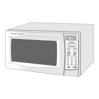
1. Insert the moulding cord stopper of power supply cord
into the square hole of the rear cabinet, referring to the
Figure C-3 (b).
2. Install the earth wire lead of power supply cord and the
earth angle to the oven cavity with one (1) screw and
tight the screw.
3. Connect the brown and blue wire leads of power supply
cord to the noise filter correctly, referring to the Pictorial
Diagram.
Figure C-3 (a). Power Supply Cord Replacement
Figure C-3 (b) Power Supply Cord Replacement
Power Supply Cord
Oven Cavity
Back Plate
Screw
Green/Yelow
Wire
Brown Wire
Fuse
Blue Wire
Noise Filter
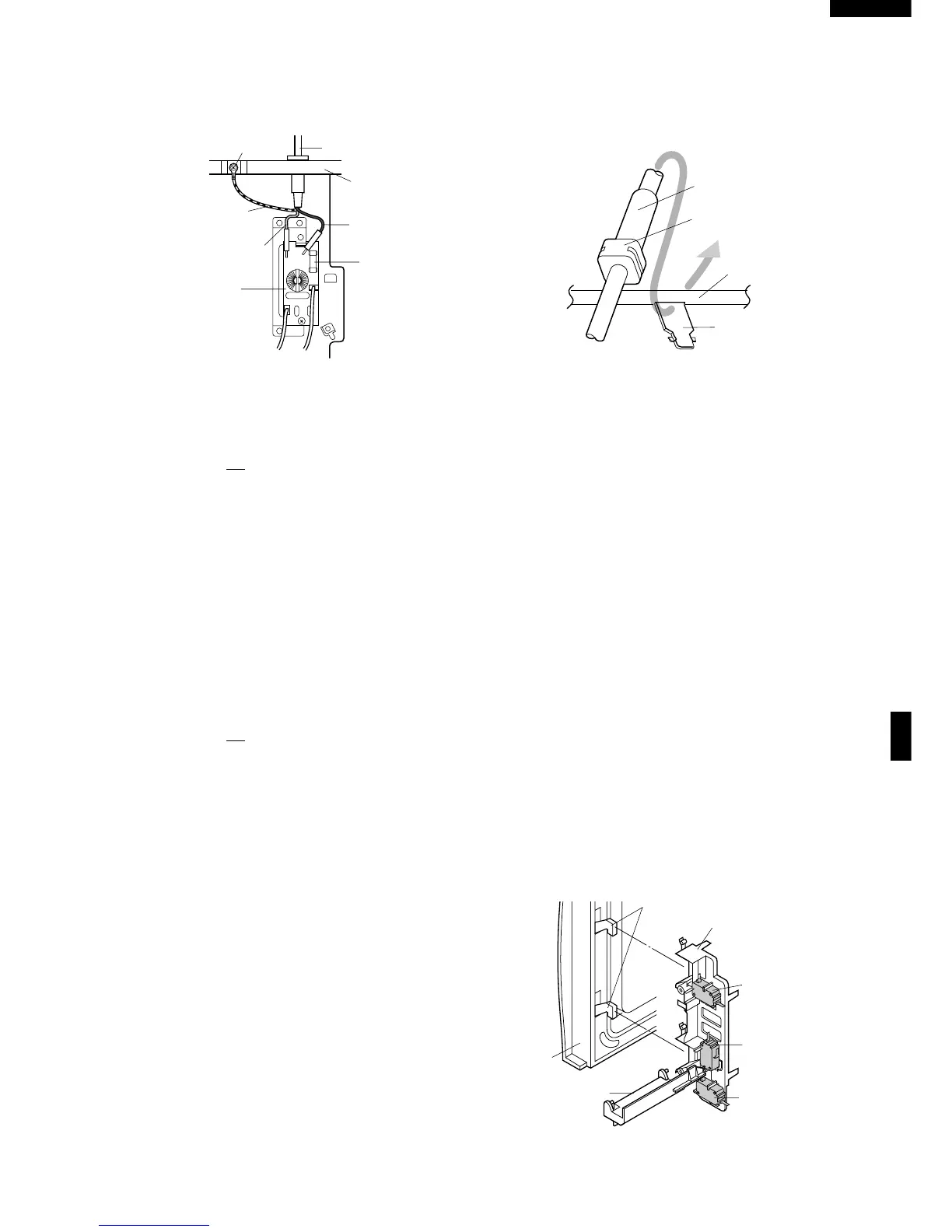
1ST. LATCH SWITCH, 2ND. INTERLOCK RELAY CONTROL SWITCH AND MONITOR
SWITCH REMOVAL
1. CARRY OUT 3D CHECKS.
2. Disconnect wire leads from the switches.
3. Remove two (2) screws holding latch hook to oven
flange.
4. Remove the switch lever from the oven cavity
5. Remove latch hook assembly from oven flange.
6. Push outward on the two (2) retaining tabs holding
switch in place.
7. Switch is now free.
Re-install
1. Re-install each switch in its place. The 1st. latch switch
and monitor switch are in the lower position and the
2nd. interlock relay control switch is in the upper
position.
2. Re-connect wire leads to each switch.
Refer to pictorial diagram.
3. Secure latch hook (with two (2) mounting screws) to
oven flange.
4. Install the switch lever to the oven cavity
5. Make sure that the monitor switch is operating properly
and check continuity of the monitor circuit. Refer to
chapter "Test Procedure" and Adjustment procedure.
1ST. LATCH SWITCH, 2ND. INTERLOCK RELAY CONTROL SWITCH AND MONITOR
SWITCH ADJUSTMENT
 Loading...