R-350D
21
CAUTION:
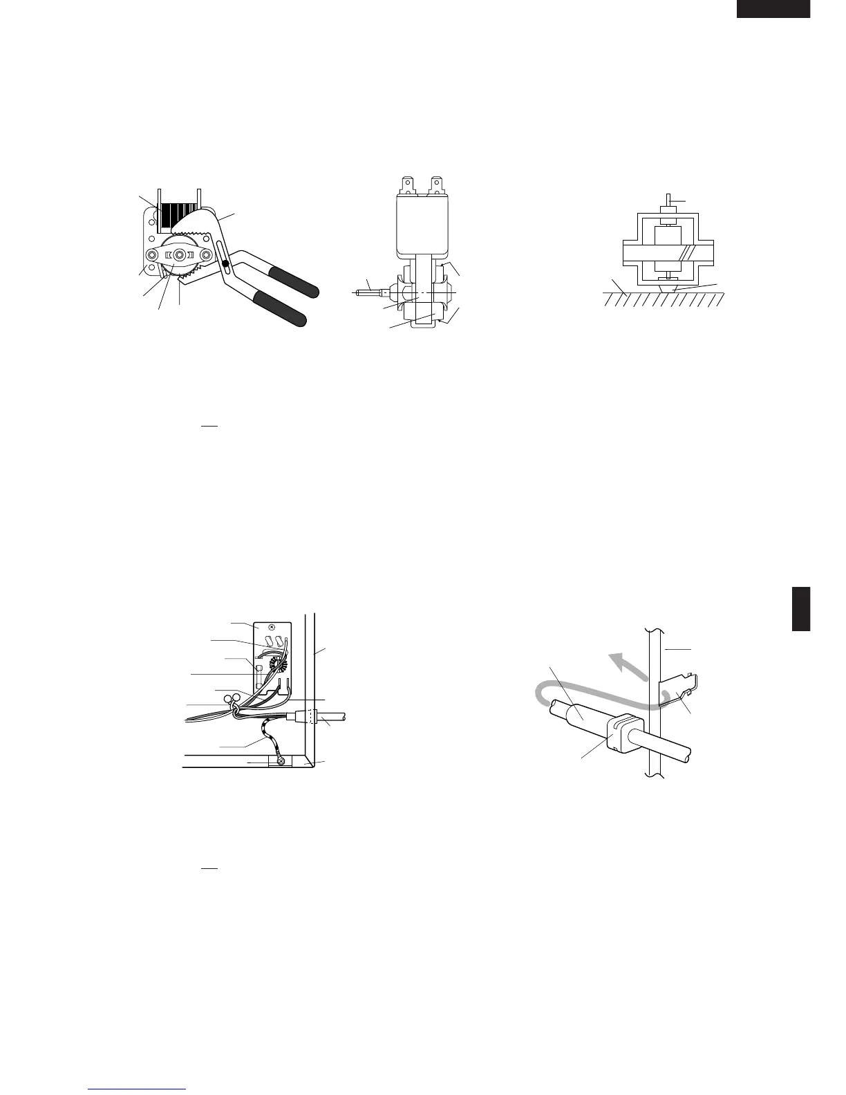
* Do not hit the fan blade strongly when installed
because the bracket may be disfigured.
* Make sure that the fan blade rotates smooth after
installation.
* Make sure that the axis of the shaft is not slanted.
3. Catch three holes of fan duct on three tabs of the
waveguide flange.
4. Install the fan duct assembly to the oven cavity with the
one (1) screw.
5. Insert the snap of the main wire harness to the hole of
the fan duct and insert the main wire harness into the
hole of the fan duct.
6. Install the chassis support and the magnetron to oven
cavity.
7. Connect the wire leads to the fan motor, referring to the
pictorial diagram.
Side View
Rear View
POWER SUPPLY CORD REPLACEMENT
1. CARRY OUT 3D CHECKS.
2. Remove the one (1) purse lock holding the wire leads
of the main wire harness and the earth wire of the
power supply cord.
3. Remove the single (1) screw holding the green/ yellow
wire to the bottom plate.
4. Disconnect the leads of the power supply cord from the
noise filter, referring to the Figure C-4 (a).
5. Release the moulding cord stopper of the power supply
cord from the square hole of the oven cavity back plate,
referring to the Figure C-4 (b).
6. Now, the power supply cord is free.
Re-install
1. Insert the moulding cord stopper of power supply cord
into the square hole of the rear cabinet, referring to the
Figure C-4 (b).
2. Install the earth wire lead of power supply cord to the
bottom plate with one (1) screw and tight the screw.
3. Connect the brown and blue wire leads of power supply
cord to the noise filter correctly, referring to the Pictorial
Diagram.
4. Hold the the wire leads of the main wire harness and
the erath wire of the power supply cord with the one (1)
purse lock.
5. Re-install outer case and check that the oven is
operating properly.
1ST. LATCH SWITCH, 2ND. LATCH SWITCH, STOP SWITCH AND MONITOR SWITCH REMOVAL
1. CARRY OUT 3D CHECKS.
2. Disconnect wire leads from the switches.
3. Remove two (2) screws holding latch hook to oven
flange.
4. Remove latch hook assembly from oven flange.
5. Push outward on the two (2) retaining tabs holding
switch in place.
6. Switch is now free.
Re-install
1. Re-install each switch in its place. The 1st. latch and
monitor switches are in the lower position and the
2nd. latch switch and stop switch are in the upper
position.
2. Re-connect wire leads to each switch.
Refer to pictorial diagram.
3. Secure latch hook (with two (2) mounting screws) to
oven flange.
4. Make sure that the monitor switch is operating properly
and check continuity of the monitor circuit. Refer to
chapter "Test Procedure" and Adjustment procedure.
Figure C-4 (a). Power Supply Cord Replacement Figure C-4 (b) Power Supply Cord Replacement
Power Supply
Cord
Oven Cavity
Back Plate
Square
Hole
Moulding
Cord Stopper
Gap
Rotor
Bracket
Stator
Groove joint pliers
Coil
Shaft
Axis
Stator
Rotor
These are the positions
that should be pinched
with pliers.
Shaft
Table
Center of
bracket
N
L
Power Supply
Cord
Oven Cavity
Back Plate
Bottom Plate
Screw
Green/Yellow Wire
Brown Wire
Blue Wire
Fuse M10A
Purse Lock
White Wire
Red Wire
Noise Filter
WHT
RED
 Loading...