R-3A54
R-3E54
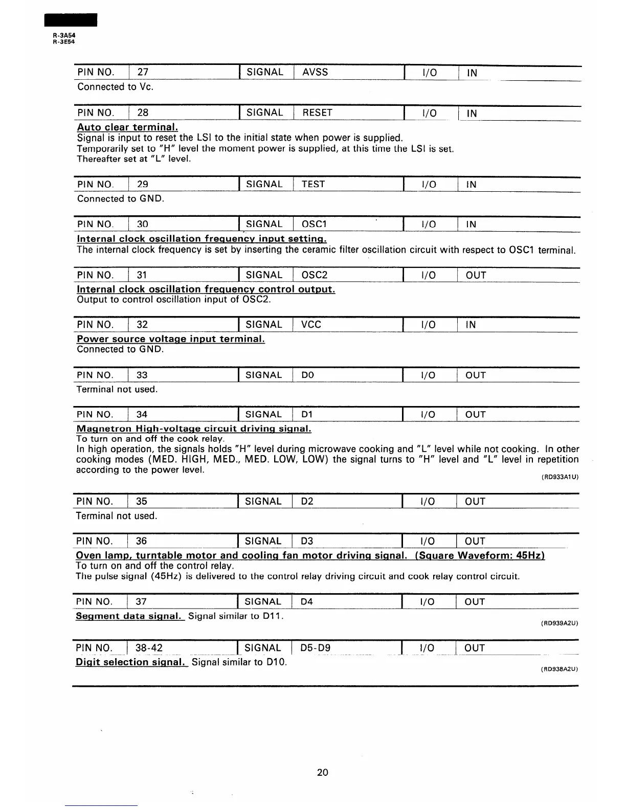
PIN NO. j 27
1 SIGNAL / AVSS
I
I/O
/ IN
Connected to VC.
PIN NO. 1 28
Auto clear terminal.
1 SIGNAL / RESET
I
l/O
IN
Signal is input to reset the LSI to the initial state when power is supplied.
Temporarily set to “H” level the moment power is supplied, at this time the LSI is set.
Thereafter set at “L” level.
PIN NO. / 29
Connected to GND.
1 SIGNAL 1
TEST
I
I/O
/ IN
PIN NO. 1 30
1 SIGNAL 1 OSCI
I
I/O
1 IN
Internal clock oscillation freauen’cv input setting.
The internal clock frequency is set by inserting the ceramic filter oscillation circuit with respect to OSCI terminal.
PIN NO. / 31 1 SIGNAL j OSC2
Internal clock oscillation frequencv control output.
Output to control oscillation input of OSC2.
I
I/O
1 OUT
PIN NO. 1 32 1 SIGNAL ) VCC
I i/O
1 IN
Power source voltage input terminal.
Connected to GND.
PIN NO.
I 33
1 SIGNAL 1 DO
1 I/O 1 OUT
Terminal not used.
PIN NO. 34 1 SIGNAL / Dl
I
I/O
1 OUT
Magnetron High-voltane circuit drivino signal.
To turn on and off the cook relay.
in high operation, the signals holds “H” level during microwave cooking and “L” level while not cooking. In other
cooking modes (MED. HIGH, MED., MED. LOW, LOW) the signal turns to “H” level and “L” level in repetition
according to the power level.
(RD933Al U)
PIN NO.
I 35
1 SIGNAL 1 D2
1 i/O 1 OUT
Terminal not used.
PIN NO.
1 36
1 SIGNAL 1 D3
1 l/O 1 OUT
Oven lamp, turntable motor and coolina fan motor driving sional. (Square Waveform: 45Hz)
To turn on and off the control relay.
The pulse signal (45Hz) is delivered to the control relay driving circuit and cook relay control circuit.
PIN NO.
I 37
1 SIGNAL 1 D4
1 I/O 1 OUT
Segment data signal. Signal similar to Dll .
(RD939A2U)
PIN NO. 1 38-42 1 SIGNAL 1 D5-D9
1 I/O 1 OUT
Digit selection signal. Signal similar to DIO.
(RD938A2U)
20
 Loading...