R-3C57
15
TEST PROCEDURES (CONT'D)
PROCEDURE
LETTER
COMPONENT TEST
N NOISE FILTER TEST
CARRY OUT 3D CHECKS.
Disconnect the leads from the terminals of the noise
filter. Using an ohmmeter, check between the terminals
as described in the following table.
L (min) Cx ± 20% Cy ± 20%
1.0 mH 0.068µF 0.0022µF
MEASURING POINT INDICATION OF OHMMETER
Between N and L Open circuit
Between terminal N and WHITE Short circuit
Between terminal L and RED Short circuit
If incorrect readings are obtained, replace the noise filter unit.
CARRY OUT 4R CHECKS.
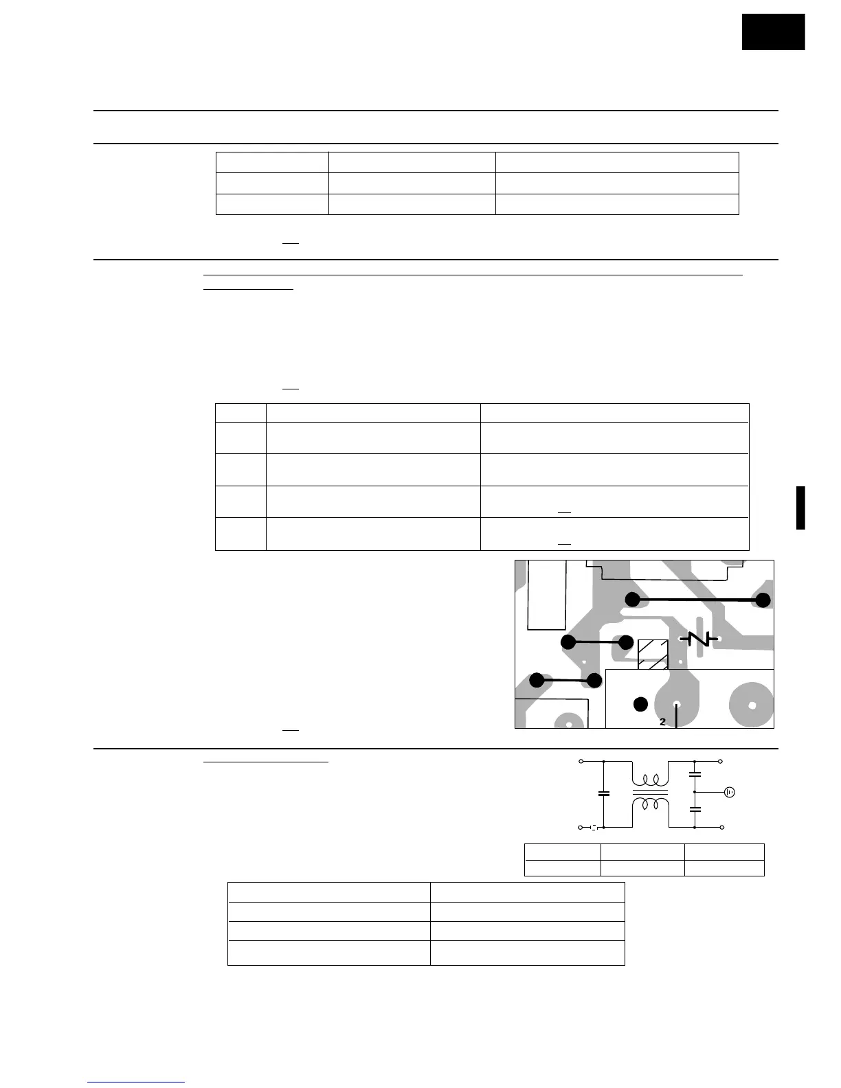
To protect the electronic circuits, this model is provided with a fine foil pattern added to the primary on
the PWB, this foil pattern acts as a fuse. If the foil pattern is open, follow the troubleshooting guide given
below for repair.
Problem: POWER ON, indicator does not light up.
CARRY OUT 3D CHECKS.
STEPS OCCURANCE CAUSE OR CORRECTION
1 The rated AC voltage is not present at Check supply voltage and oven power cord.
POWER terminal of CPU connector (CN-H)
2 The rated AC voltage is present at primary Low voltage transformer or secondary circuit defective.
side of low voltage transformer. Check and repair.
3 Only pattern at "a" is broken. *Insert jumper wire J1 and solder.
(CARRY OUT
3D CHECKS BEFORE REPAIR)
4 Pattern at "a" and "b" are broken. *Insert the coil RCILF2003YAZZ between "c" and "d".
(CARRY OUT
3D CHECKS BEFORE REPAIR)
NOTE: *At the time of making these repairs, make
a visual inspection of the varistor. check
for burned damage and examine the
transformer with a tester for the presence
of layer short-circuit (check primary coil
resistance). If any abnormal condition is
detected, replace the defective parts.
CARRY OUT 4R CHECKS.
M PROCEDURES TO BE TAKEN WHEN THE FOIL PATTERN ON THE PRINTED WIRING BOARD
(PWB) IS OPEN
RELAY SYMBOL OPERATIONAL VOLTAGE CONNECTED COMPONENTS
RY1 APPROX. 25.0V D.C. Oven lamp / Turntable motor / Cooling fan motor
RY2 APPROX. 29.0V D.C. Power transformer
CARRY OUT 4R CHECKS.
 Loading...