13
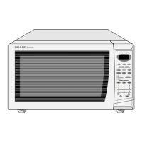
R-509FW
1-2 VL2-VL1 IN Power source voltage input terminal.
Standard voltage for LCD.
3-6 AN7-AN4 IN
Terminal to change cooking input according to the Model.
By using the A/D converter contained in the LSI, DC voltage in accordance with the
Model in operation is applied to set up its cooking constant.
7 P63 OUT Terminal not used.
8 AN2 IN
Input terminal to judge the model.
Connected to GND through the pull-down resistor.
9 AN1 IN To input signal which communicates the door open/close information to LSI.
Door close “H” level signal (0V). Door open “L” level signal (-5V).
10 AN0 IN Input terminal to judge the model.
The one of signals P20 - P27 will be input into AN0 through one of G1 - G8 lines on
key matrix.The LSI will judge the model by this signal.
11 P57 OUT Back light circuit (Light emitting diodes) driving signal.
12-13 P56-P55 OUT Terminal not used.
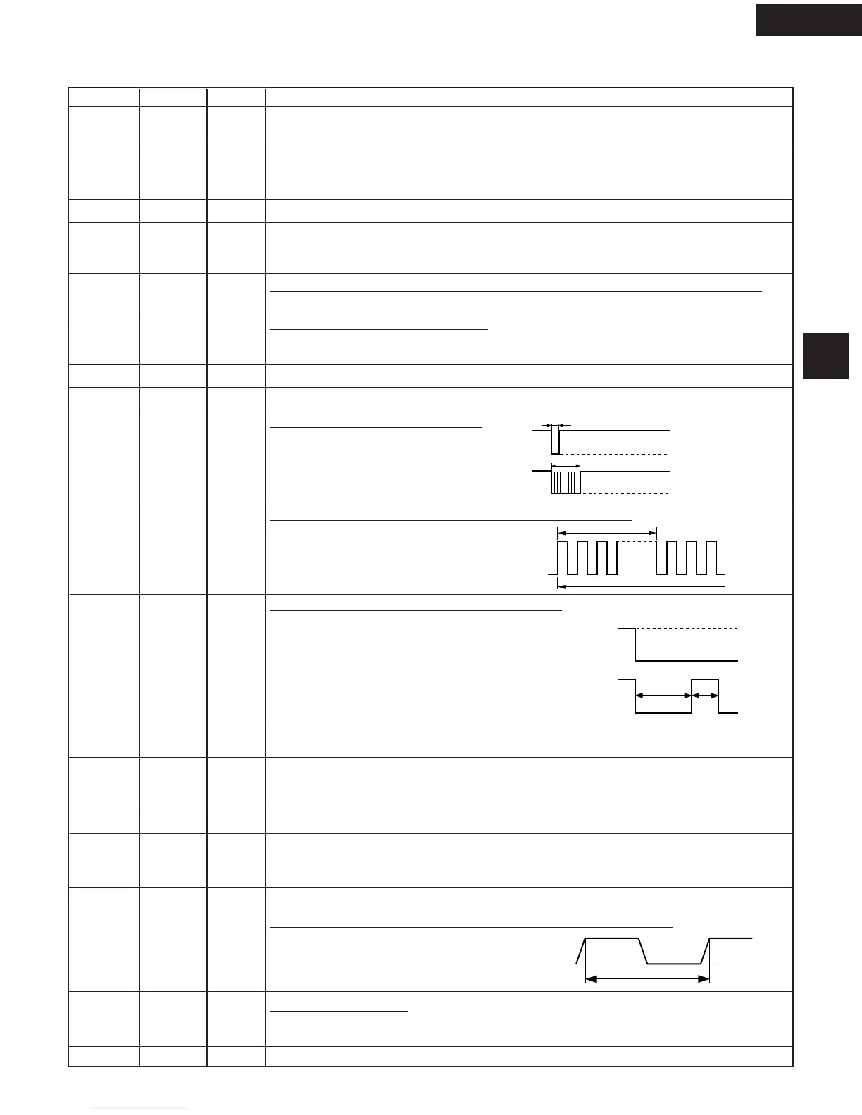
14 CNTR0 OUT Signal to sound buzzer (2.0 kHz).
A: key touch sound.
B: Completion sound.
15 P53 OUT Oven lamp, fan motor and turntable motor driving signal
To turn on and off shut off relay (RY1). The
square waveform voltage is delivered to the
RY1 driving circuit and RY2 control circuit.
16 P52 OUT Magnetron high-voltage circuit driving signal.
To turn on and off the cook relay (RY2).
The signals holds “L” level during
microwave cooking and “H” level while
not cooking. In other cooking modes
(variable cooking) the signal turns to “H”
level and “L” level in repetition according
to the power level.
17-18 P51-P50 OUT Terminal not used.
19 P47 IN Signal coming from touch key.
When either G12 line on key matrix is touched, a corresponding signal out of P20 -
P27 will be input into P47. When no key is touched, the signal is held at “H” level.
20 P46 OUT Terminal not used.
21 P45 IN Signal similar to P47.
When either G11 line on key matrix is touched, a corresponding signal will be input
into P45.
22-23 P44-P43 IN Terminal not used.
24 INT0 IN Signal synchronized with commercial power source frequency.
This is the basic timing for time processing of LSI.
25 P41 IN Signal similar to P47.
When either G10 line on key matrix is touched, a corresponding signal will be input
into P41.
26 P40 IN Connected to GND through the pull-down resistor R90.
LSI
The I/O signal of the LSI is detailed in the following table.
Pin No. Signal I/O Description
DESCRIPTION OF LSI
A
B
0.1 sec.
2.0 sec.
H : GN
 Loading...