21
R-84ST -
O RELAY TEST
TEST PROCEDURES
P PROCEDURES TO BE TAKEN WHEN THE FOIL PATTERN ON THE PRINTED WIRING BOARD
(PWB) IS OPEN
NOTE: *At the time of these repairs, make a
visual inspection of the varistor for burn-
ing damage and examine the trans-
former with tester for the presence of
layer short circuit (check primary coil
resistance).
If any abnormal condition is detected,
replace the defective parts.
CARRY OUT 4R CHECKS.
To protect the electronic circuits, this model is provided with a fine foil pattern added to the input circuit on
the PWB, this foil pattern acts as a fuse. If the foil pattern is open, follow the troubleshooting guide given
below for repair.
Problem: POWER ON, indicator does not light up.
CARRY OUT
3D CHECKS.
STEPS OCCURRENCE CAUSE OR CORRECTION
1 The rated AC voltage is not present between Check supply voltage and oven power cord.
Pin Nos. 1 and 3 of the 4-pin connector (E).
2 The rated AC voltage is present at primary Low voltage transformer or secondary circuit defective.
side of low voltage transformer. Check and repair.
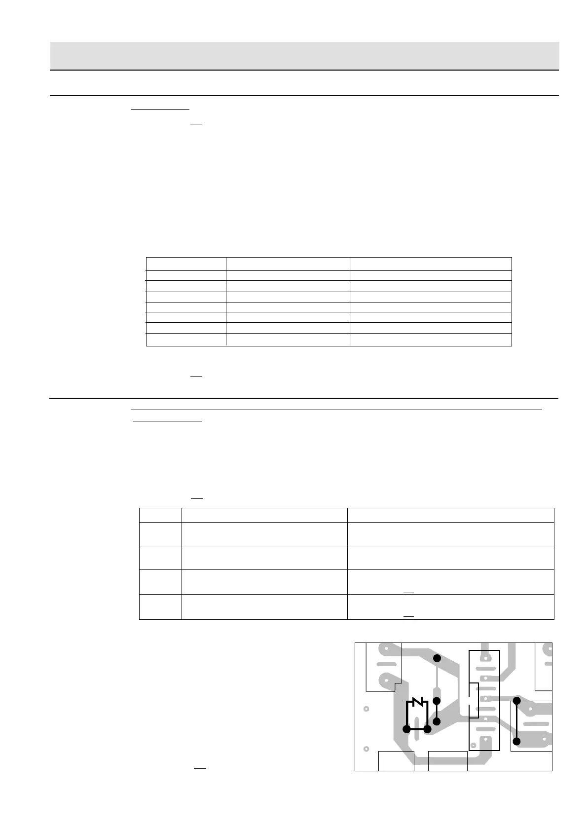
3 Only pattern at "a" is broken. *Insert jumper wire J1 and solder.
(CARRY OUT 3D CHECKS BEFORE REPAIR.)
4 Pattern at "a" and "b" are broken. *Insert the coil RCILF2003YAZZ between "c" and "d".
(CARRY OUT 3D CHECKS BEFORE REPAIR.)
CARRY OUT 3D CHECKS.
Remove the outer case and check voltage between Pin Nos. 1 and 3 of the 4 pin connector (E) on the control
unit with an A.C. voltmeter.
The meter should indicate 230-240 volts, if not check oven circuit.
Relay Test
Check voltage at the relay coil with a D.C. voltmeter during the microwave cooking operation, grill
operation, convection operation or dual operation.
DC. voltage indicated............. Defective relay.
DC. voltage not indicated ....... Check diode which is connected to the relay coil. If diode is good, control
unit is defective.
RELAY SYMBOL OPERATIONAL VOLTAGE CONNECTED COMPONENTS
RY1 Approx. 18.0V D.C. Oven lamp / Turntable motor
RY2 Approx. 18.0V D.C. High voltage transformer
RY3 Approx. 24.0V D.C. Grill (Top) heating element
RY4 Approx. 24.0V D.C. Bottom heating element
RY5 Approx. 24.0V D.C. Touch control transformer
RY6 Approx. 24.0V D.C. Fan motor
RY7 Approx. 24.0V D.C. Convection motor
CARRY OUT 4R CHECKS.
7
9
1
RY4
(J1)
(J2)
FM
POWER
a
b
c
d
F
CN - E
CN - A
VRS1
RY6
PROCEDURE
LETTER COMPONENT TEST
 Loading...