UM353-1B Installation
April 2012
7-17
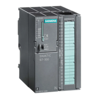
7.4.7 Ohms and Slidewire Input Wiring
Function blocks AINU1 and AINU2 can be configured for ohm or slidewire inputs. Figure 7-16 shows the needed
connections for Ohm and Slidewire inputs.
45
46
47
48
Controller Circuitry
Isolated
Power
Isolated
Ground
Universal
Converter,
Isolated
Inputs
Note: See Table 7-1 for AINU2 terminals.
Ohms
Source
MG00514a
Controller Terminals
45
46
47
48
Controller Circuitry
Isolated
Power
Isolated
Ground
Universal
Converter,
Isolated
Inputs
Note: See Table 7-1 for AINU2 terminals.
Position
Slidewire
MG00515a
Jumper
Controller Terminals
Ohm Input Slidewire Input
Figure 7-16 Universal Analog Input, AINU1 Shown
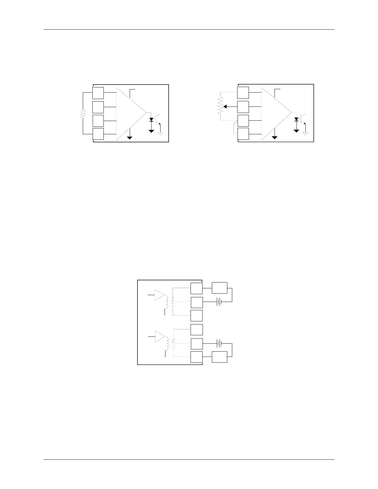
7.4.8 Relay Output Wiring
Function blocks ROUT1 and ROUT2 are located on the I/O Expander board. They provide two single-pole,
double-throw relay outputs, as shown in Figure 7-17. Relay contact ratings are stated in Section 13.6 MPU
Controller Board Specifications.
The load connected to a closed contact should draw a current between the minimum and maximum contact ratings.
A resistive load is recommended. An inductive or capacitive load can cause high peak currents or contact arcing
which can pit or otherwise damage contacts. The arcing associated with an inductive load can be limited by
connecting a voltage transient suppressor, such as a 1N4005 diode, across the load.
Figure 7-17 Universal Relay Outputs ROUT1 and 2, Resistive Load
27
28
Model 353
Rear Terminals
29
Controller Circuitry
X03120S0
NC
NO
30
31
32
NC
NO
ROUT1
ROUT2
Load
Load
+
_
+
_
External
Power
Supply

 Loading...