Function Blocks UM353-1B
April 2012
3-16
3.2.8 AIN_ - Analog Inputs
AIN_ function blocks convert a voltage input, having a
range defined during calibration, into a block output signal
that is scaled in engineering units. The output is then
interconnected to other function blocks within the
controller.
A 6-character ASCII value can be entered to identify the
engineering units of the output signal. The scaled output
range is configurable and has a factory default of 0.0 to
100.0 PRCT. Ranges such as 300.0 to 500.0, representing
engineering units in degrees C, can also be configured.
The Output Range is a special data type that includes the
MIN and MAX SCALE, the DPP, and the ENGUNITS
that can be connected to other blocks with a Range (RG
PTR) input.
Analog Input blocks are available on the MPU Controller
Board (CB) and on the I/O Expander Board (EB). Block names (IDs) are listed in Section 7.4 Electrical Installation
together with the case rear terminal numbers. Power for 2-wire transmitters is available at the rear terminals.
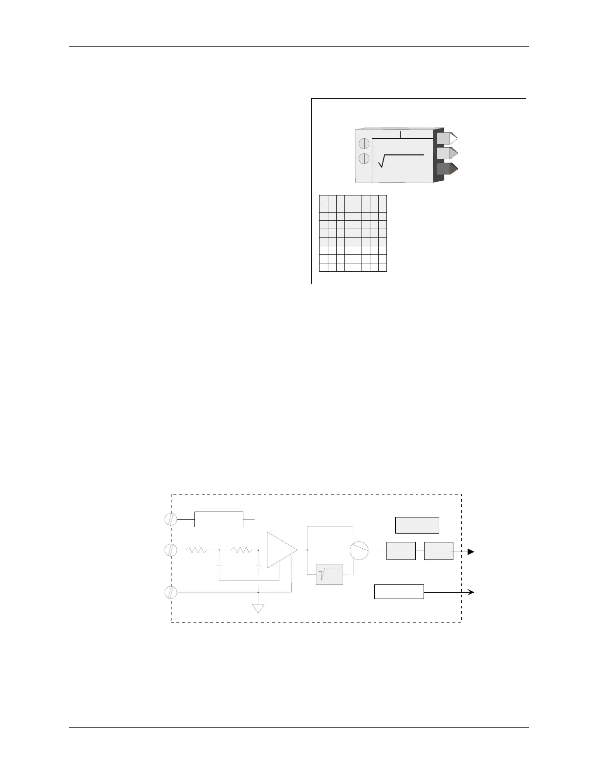
A digital filter (time constant) is available to dampen process noise. A square root extractor is also available to
linearize a flow signal from a ΔP transmitter, allowing the block output to be configured for flow units. Output QS
indicates the quality of the analog output signal O1, and will be high (1) when output O1 is bad, and low (0) when
good. Bad quality signifies an A/D conversion failure or a 1-5Vdc input signal that falls below 0.7 Vdc indicating
an open circuit or failure of a 2-wire transmitter.
A verify mode (CAL VIEW) is available during calibration to view the block output over the full calibrated range.
The input is factory calibrated for 1-5 Vdc and should not require field calibration. However, field calibration can
be performed if another range is required or to match the exact transmitter calibration. Current inputs are
accommodated using precision dropping resistors connected across the input terminals (250Ω resistors are supplied
with the controller for conversion of 4-20mA inputs).
Power Up - During a hot, a warm or a cold start, the function block will temporarily by-pass the digital filter to
enable the output to initialize at the actual hardware input signal.
AIN_+
AIN_c
ANALOG INPUT _
I
N
S
E
C
A
M
S
I
C
F
L
E
T
L
C
C
S
Q
RT
Z
ER
O
FLL
V
E
I
W
MIN
imum
SCALE
(H)
.................. Real (0.0)
MAX
imum
SCALE
(H)
................. Real (100.0)
DIG
ital
FILT
er
(S)
............. 0 to 180 sec (0 sec)
SQ
uare
ROOT
extractor
(S)
.... N0/YES (NO)
ZERO
input
(C)
.................. 0 to 1.0 Vdc
FULL
scale input
(C)
...... 4.0 to 5.0 Vdc
VIEW
input - verify cal.
(C)
............ Real
OR
O
utput
R
ange
ANALOG INPUT
EXTRACTOR
U
AIN_
L
A
X
D
I
G
OO
C
A
L
L
A
A
L
M
A
QS
Q
uality
S
tatus
EN
GU
N
I
TS
D
ecimal
P
t.
P
osition (preferred)
(S)
.. 0.0.0.0.0.0 (0.00)
DPP
ENG
ineering
UNITS
(S)
.. 6 Char ASCII (PRCT)
O1
O
utput
1
A/D
XTR
C1 C2
R1
R2
NO
YES
O1
Digital
Filter
Scaling
Current Limit
+ 24 Vdc
QS
Quality Test
AI_+
AI_c
xmtr+
ENG UNITS
.

 Loading...