Interrupter/Operator Description
1273-94
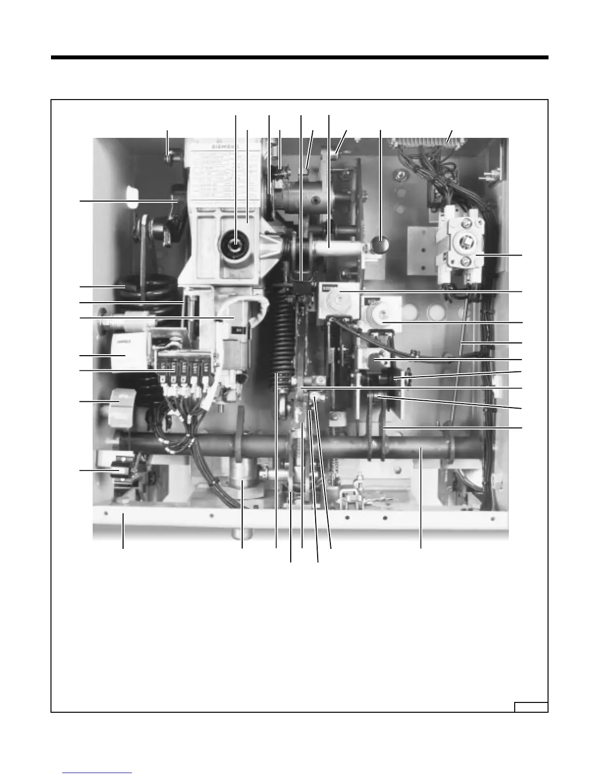
Figure 6. Stored Energy Operating Mechanism
50 Manual spring charging crank
50.1 Manual spring charging access hole
50.2 Charging mechanism gear box
50.3.1 Driver
50.4 Spring charging motor
50.4.1 Limit switches
53 Close pushbutton
53.1 Spring release coil 52SRC
54 Trip pushbutton
54.1 Shunt trip coil 52T
55 Close-open indicator
55.1 Linkage
55.2 Control Lever
58 Closing spring charge indicator
59 Operation counter
61.8 Shock absorber
62 Closing spring
62.2 Crank
62.3 Cam disc
62.5 Lever
62.5.2 Latching pawl
62.6 Drive lever
62.8 Trip free coupling rod
62.8.1 Spring return latch
62.8.2 Trip free coupling link
62.8.3 Trip free coupling lever
63 Jack shaft
63.1 Lever
63.5 Lever
63.7 Lever
64 Tripping spring
64.1 Pawl
64.2 Pawl
64.3 Lever
64.3.1 Pawl roller
68 Auxiliary switch
68.1 Link
60 61.8 64
63.5
62.8
62.8.3 (behind 62.8)
62.8.2 63
68
53.1
68.1
54.1
54
64.1
62.8.1
64.2
64.3
55.2
50.1
50.2
50.3
50.3.1
62.6
62.3
62.5.2
62.5
53
68.7
55.1
62
62.2
50.4.1
58
50.4
59
55
9
 Loading...


