9229 0037 174 0-
2010-03-22
5-2
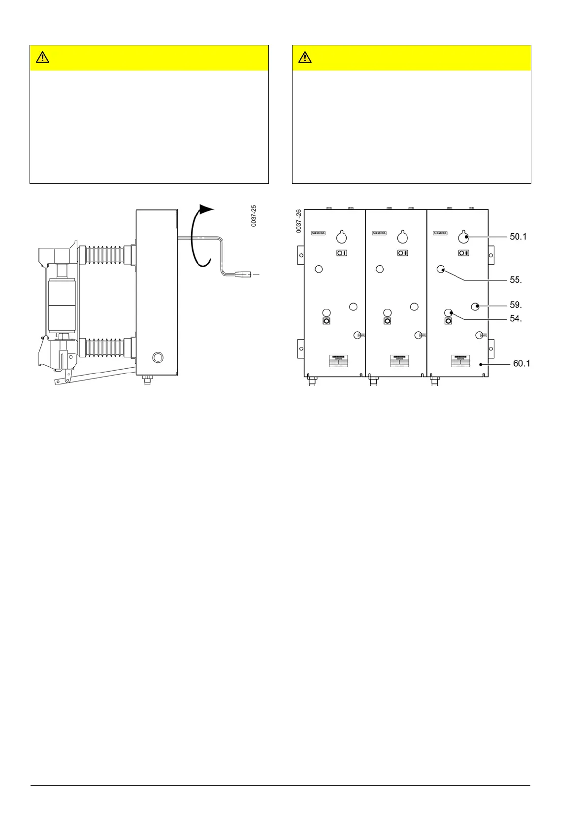
50.1 Öffnung für Handkurbel
54. Druckknopf AUS
55. Federzustandsanzeige
59. Schaltstellungsanzeige
60.1 Abdeckung
Fig. 5/1 Einschalten des V-Schalters 3AH5
4. Beim V-Schalter 3AH5 mit Unterspannungsauslöser (Y7)
3AX1103 ist zusätzlich die Arretierungsschraube des
Schlagbolzens von Stellung A nach B zu versetzen (siehe
Hinweiskarte im Antriebskasten des V-Schalters 3AH5).
Dazu die 4 Befestigungsschrauben der Abdeckung (60.1)
entfernen, Abdeckung öffnen und nach Abschluss der
Arbeiten die Abdeckung (60.1) in umgekehrter Reihen-
folge montieren.
5. Zum Probeschalten Niederspannungsstecker kundensei-
tig anschließen und Versorgungsspannung einschalten.
Der Motor spannt automatisch die Einschaltfeder und
wird nach erfolgtem Spannvorgang automatisch intern
abgeschaltet.
Alternativ kann die Einschaltfeder mit der Handkurbel,
über die Kupplung (50.1), gespannt werden (ca. 20
Umdrehungen), bis ein hörbares Klicken die Verklinkung
anzeigt.
• In der Federzustandsanzeige (55.) wird das Symbol
„Einschaltfeder gespannt“ sichtbar.
• Den V-Schalter elektrisch einschalten.
• Die Schaltstellungsanzeige (59.) wechselt von „AUS“ in
„EIN“.
• Die Federzustandsanzeige (55.) wechselt auf „Ein-
schaltfeder entspannt“.
• Bei anliegender Versorgungsspannung wird die Ein-
schaltfeder sofort wieder vom Motor gespannt und die
VORSICHT
Verletzungsgefahr bei Einsatz falscher Hilfsmittel zum
Spannen der Einschaltfeder.
Bei anliegender Versorgungsspannung spannt der
Motor nach dem Einschalten die Einschaltfeder sofort
wieder nach.
Der V-Schalter darf nur mit der Originalhandkurbel (gehört
nicht zum Lieferumfang) aufgezogen werden, um Verlet-
zungen durch den plötzlich anlaufenden Motor zu vermei-
den.
50.1 Opening for hand crank
54. “OPEN” pushbutton
55. Spring state indicator
59. “CLOSED/OPEN” indicator
60.1 Cover
Fig. 5/1 Closing the 3AH5 vacuum circuit-breaker
4. On the 3AH5 V-breaker with undervoltage release (Y7)
3AX1103, the arresting screw of the hammer must be
moved from position A to B (see instruction card in the
mechanism housing of the 3AH5 vacuum circuit-breaker).
In addition loose the screws of the cover (60.1) and open it.
Mount the cover (60.1) after the end of work again.
5. Connect the low-voltage plug connector on the customer
side and close the supply voltage for test switching.
The motor charges the opening spring automatically is
deactivated internally and automatically after the execut-
ion of the charging process.
The closing spring can be charged automatically, by the
coupling (50.1), which is activated by a crank-handle (ca
20 revolutions) until an audible clicking indicates the acti-
vation of the latching.
• The spring state indicator (55.) indicates the symbol
"closing spring charged".
• Close the V-breaker electrically.
• The "CLOSED/OPEN" indicator (59.) switches from
"CLOSE" to "OPEN".
• The Spring state indicator (55.) indicates "closing spring
discharged".
• When the supply voltage is applied the closing spring
gets charged by the motor and the spring state indicator
CAUTION
Risk of injury by using wrong aids for charging the
closing spring.
When the supply voltage is applied, the motor imme-
diately recharges the closing spring.
The V-breaker may be operated only with the original hand
crank (if fitted as an additional feature), in order to avoid
injuries that may occur if the motor starts up suddenly.

 Loading...


