2
2. Connect the 4-wire cable included in the installation
kit to the 4-position header on the FP2011-U1. The
cable is keyed and will connect in only one way.
Connect the other end of the cable to the terminal
block (TB) indicated in the system installation
manual. This cable is also keyed and will connect
in only one way. (Refer to Figure 3.)
FP2011-U1
Black (L)
White (N)
Green (G)
LNG
AVANT ENTRETIEN
DESACTIVEZ L'UNITE
REMOVING
TERMINAL
BLOCK PROTECTION
DISCONNECT POWER
PRIOR TO
WARNING
AC
Mains
SUPERVISED
NON-POWER
LIMITED
18 AWG MIN.
4-POSITION
HEADER
Figure 2
Wiring the FP2011-U1
MATES WITH
FP2011-U1
POWER SUPLY
MATES WITH CONNECTOR
ON PCB BOARD
Blue
Black
Black
Red
FERRITE
CORE
Figure 3
FP2011-U1 Power Supply Cable
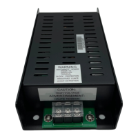
ELECTRICAL RATINGS
Primary Power:
Input: 120VAC or 240VAC,
50/60Hz @ 2.0A Max.
Output: 26VDC @ 6.5A Max.
Max Current: 6.5A (2 Hours Max.)
Filtered and Regulated
JUMPER REMOVAL FOR 240VAC ONLY
Remove all system power before installa-
tion, first battery then AC. (To power up,
connect the AC first, then the battery.)
If the AC input is 240VAC, you will need to remove
the cover of the FP2011-U1 housing and remove the
jumper on J1. Follow the steps listed below.
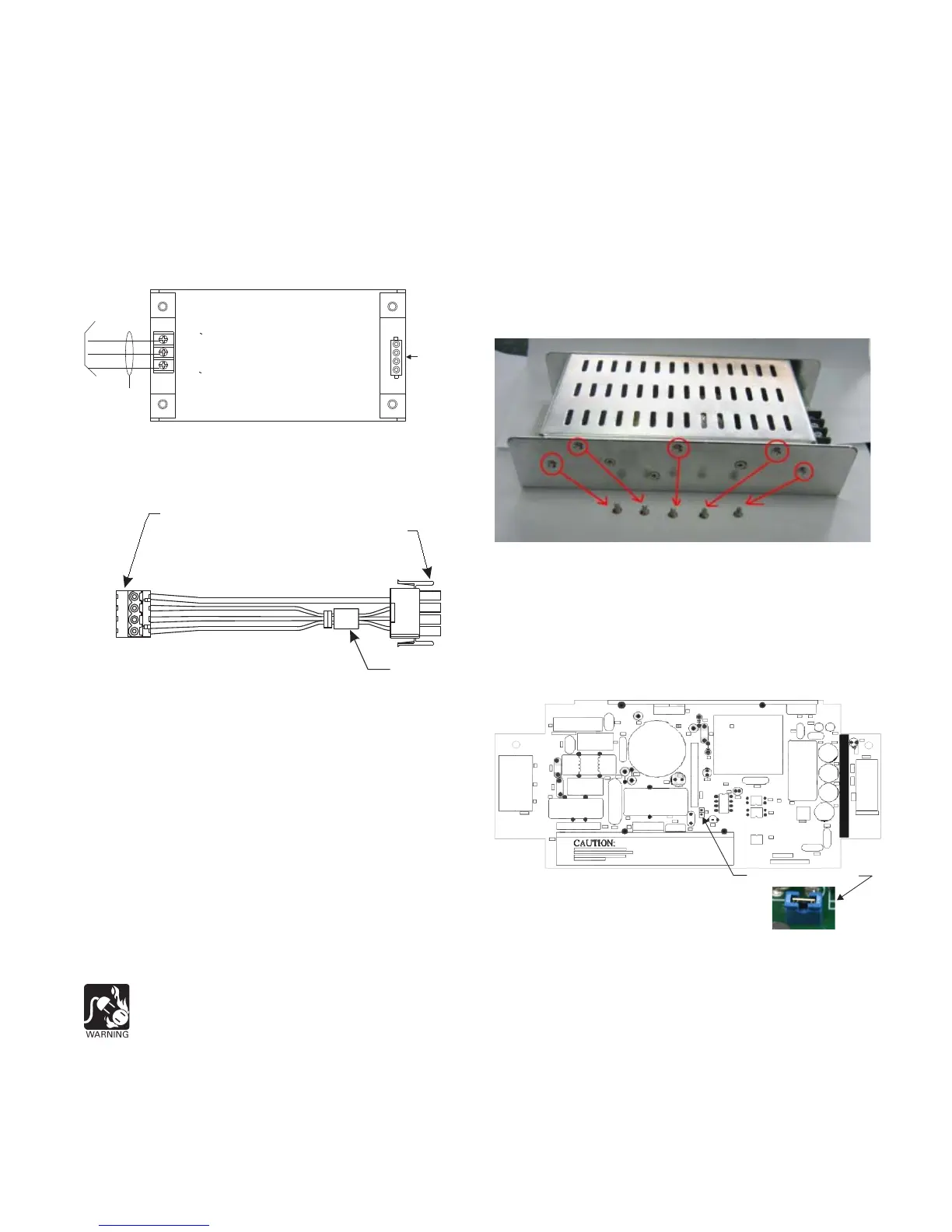
1. On the side of the housing with 5 screws, remove
all 5 screws and place them to one side.
2. On the side of the housing with 8 screws, remove
the 5 screws indicated in Figure 4 and place them to
one side.
DO NOT REMOVE THE REMAINING 3 SCREWS.
Figure 4
Removing 5 Screws from the Side of the
FP2011-U1 that has 8 Screws
3. Take off the top cover.
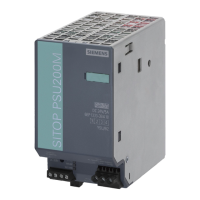
4. Locate jumper J1. Refer to Figure 5 to find the
location.
FP2011-U1 PCB
For 240VAC, Remove Jumper
Figure 5
Location of Jumper J1 for 120VAC on the FP2011-U1
Power Supply (For 240VAC, Remove Jumper)
5. Remove J1 by hand or by using a tool.
6. Replace the top cover on the FP2011-U1 and
secure in place by installing the 10 screws that
were removed.
P/N 315-050222-2