163/301
Siemens Building Technologies Basic Documentation LMV5... CC1P7550en
HVAC Products 8 Commissioning instructions for the LMV5... system 13.08.2004
8.1.4 Extra functions of the LMV5...
Menu level 1 Menu level 2 Menu level 3 Menu level 4 Menu level 5 Menu level 6
Params & Display
BurnerControl
ValveProving
ValveProvingType
Config_PM-VP/CPI
VP_EvacTme
VP_TmeAtmPress
VP_FillTme
VP_Tme_GasPress
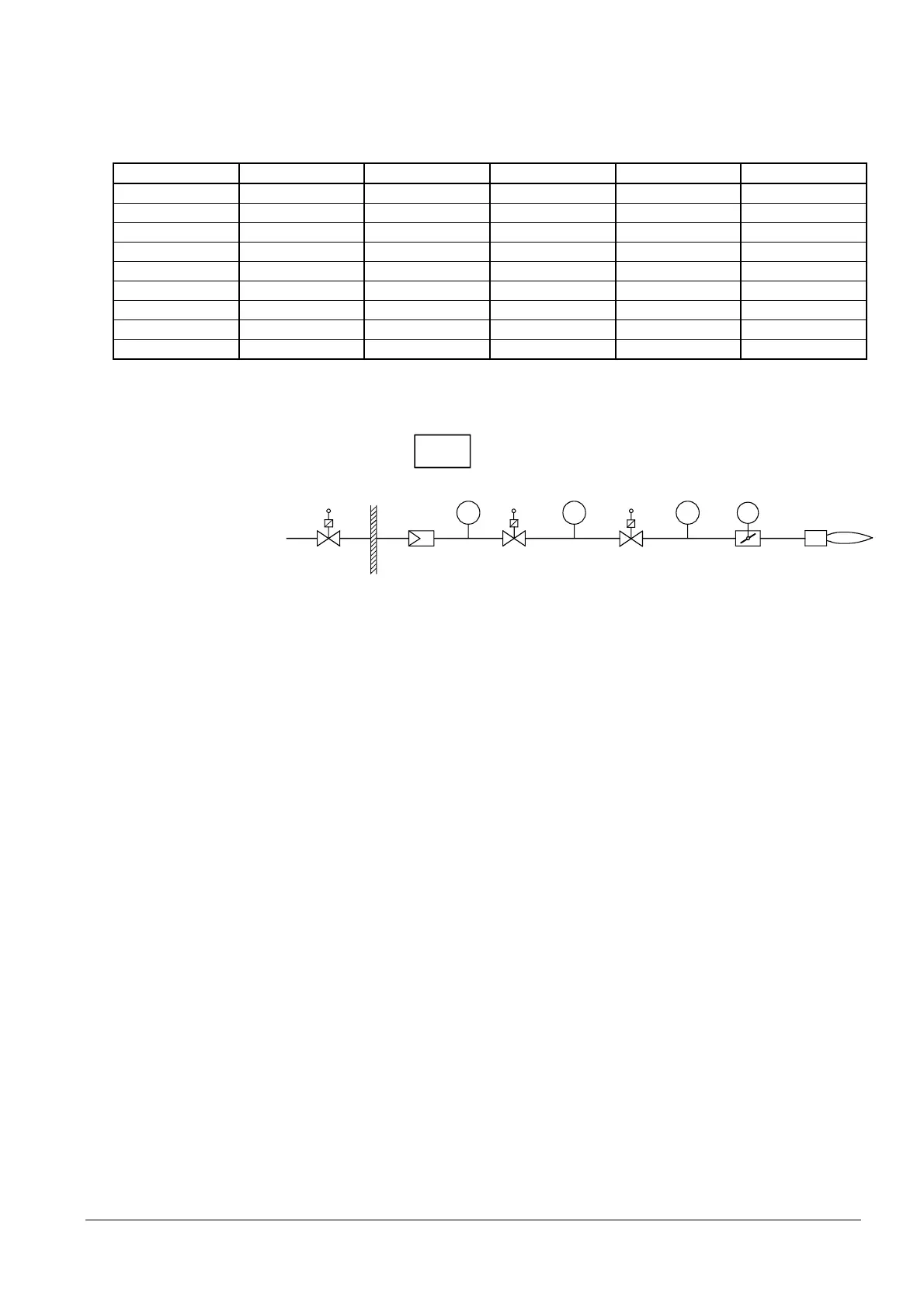
The gas volume contained in the piping between the valves (including the valve vol-
ume) must be calculated in accordance with the gas train.
SV
V1
V2
Direct ignition
G
Program
7550s01E/0202
ACT
PS
max
PS
min
PS
VP
Determination of the test time with predefined leakage rate to be detected during
valve proving:
(P
G
- P
w
)
• V • 3600
t
Test
=
⎯⎯⎯⎯⎯⎯⎯⎯⎯
P
atm
• Q
Leck
Determination of the detected leakage rate during valve proving:
(P
G
- P
w
)
• V • 3600
Q
Leck
=
⎯⎯⎯⎯⎯⎯⎯⎯⎯
P
atm
• t
Test
Q
Leck
in l / h Leakage rate in liters per hour
P
G
in mbar
Overpressure between the valves at the beginning of the test phase
P
W
in mbar Overpressure set on the pressure switch (normally 50 % of the
gas inlet pressure)
P
atm
in mbar
Absolute air pressure (1,013 mbar normal pressure)
V in l Volume between the valves (test volume)
including valve volume and pilot path (Gp1) if present
t
Test
in s Test time
27. Valve proving (leak-
age test LT)
Example of fuel train
Legend
 Loading...
