Document No: 129-612
Installation Instructions
January 19, 2016
Page 2 of 3 Siemens Industry, Inc.
Mounting an Actuator to a Valve
1. If you are attaching the actuator to a new valve,
remove the protective plastic cap from the valve
stem.
2. On the SAS61.03U Actuator, turn the manual-
positioning knob counterclockwise to its end
point.
3. Place the actuator on the valve.
4. Hand-tighten the coupling piece.
5. Use either a Phillips head screwdriver or a flat-
blade screwdriver to remove the actuator cover
for access to the terminal block.
6. Attach wires. See Wiring and Start-Up.
7. Place the cover on the actuator.
8. Fasten the cover with the screws.
Wiring
All wiring must conform to NEC and local codes and
regulations.
Use earth ground isolating, step-down Class 2
transformers. Do not use auto transformers.
Determine the supply transformer rating by adding the
total VA of all actuators used. The maximum rating for
Class 2 step-down transformer is 100 VA. It is
recommended that no more than 10 actuators be
powered by one transformer.
1. Remove actuator cover screws using either a
No. 2 Phillips or a No. 2 flat-blade screwdriver
and detach actuator cover.
2. Access terminal block and attach wires per
Figure 2.
3. Replace actuator cover. Use cover screws to
secure actuator cover in place.
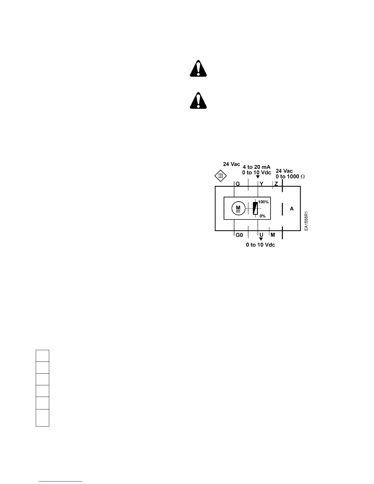
G0
Neutral (-)
G
Hot (+)
Y
Positioning signal for 0 to 10 Vdc/4 to 20 mA
M
Measuring neutral
U
Position feedback 0 to 10 Vdc
Z
Positioning signal forced control AC/DC ≤ 24V,
0 to 1000 Ω
Figure 2. Terminal Connections.
Terminal connection G is 24 Vac HOT, not
ground.
• G0 and G must be properly wired for
correct function and full life of the
actuator.
• If the actuator makes a buzzing noise
upon reaching setpoint, G and G0 are
improperly wired and should be
reversed.
Figure 3. Wiring Diagram.
The diagram shows all possible connections. The
application determines which connections are used.
Start-Up
The valve body (normally open or normally closed)
determines the action of the complete valve/actuator
assembly.
Troubleshooting
• Check wiring for proper connections and secure
attachments.
• Check for adequate power supply.
References
Powermite 599 MT Series SAS Electronic Valve
Actuators, 24 Vac or 24 Vdc, Proportional Control
Technical Instructions (155-682).

 Loading...