Installation Instructions
Document No. 129-413
October 13, 2004
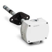
Q-Series Relative Humidity (RH) and
Relative Humidity & Temperature (RH/T) Duct Sensors
Product Description
Relative Humidity (RH) and Relative Humidity &
Temperature (RH/T) duct sensors monitor the
relative humidity or the relative humidity and
temperature in a duct, depending on the model.
Sensors are directly wired to the controller via
twisted pair and/or three conductor cables
(18 to 22 AWG). The number and type of cables
required depends on the model selected. All field
wiring is terminated in a terminal block on the sensor
body.
Product Numbers
Table 1. Relative Humidity Only.
Product
Number
Humidity
Signal
Accuracy
♦
QFM2100 ±5%
QFM3100
0 to 10 Vdc
±2%
QFM2101 ±5%
QFM3101 ±2%
QFM4101
4 to 20 mA
±2% Certified
Table 2. Relative Humidity and Temperature.
Product
Number
Temperature
Signal
Humidity
Signal
Accuracy
♦
QFM2160 ±5%
QFM3160 ±2%
QFM4160
0 to 10 Vdc 0 to 10 Vdc
±2% Cert.
QFM2171 ±5%
QFM3171 ±2%
QFM4171
4 to 20 mA 4 to 20 mA
±2% Cert.
QFM2110
Pt 1KΩ
QFM2120
Ni 1KΩ
QFM2140 T1 PTC
±5%
QFM3110
Pt 1KΩ
0 to 10 Vdc
±2%
♦
Applies to humidity only
NOTE: Sensor tips on QFM31… and QFM41…
models are field replaceable.
Additional Reference Documents
Product Number Technical Instructions
QFM21… 155-748
QFM3160 155-749
QFM4160 155-750
Required Tools
• Phillips screwdrivers, #1 and #2
• Wire cutters/strippers
• Medium flat-blade screwdriver
• Tape measure
• Medium-duty electric drill
• Marker or pencil
• No. 26 (0.147-inch) drill bit
• Small level
• 7/8-inch drill bit or hole saw
• Two No. 8 × 1-inch sheet metal screws
Expected Installation Time
One hour
Prerequisites
• Ensure that the appropriate field wiring is
installed.
Appropriate wiring is one or more twisted
pairs, or three conductor cables (plenum or
non-plenum as required), within the
maximum wiring run length for the individual
equipment controller. The maximum
recommended length is 750 feet (229 m).
• Ensure that all wiring complies with National
Electric Code (NEC) and local regulations.
Mounting Information
Locate the sensor:
• In the center of a duct.
• Away from fans, corners, heating and cooling
coils, and so on.
• Where it receives adequate airflow for proper
operation.
Item Number 129-413, Rev. 011 Page 1 of 3