Alle benutzerdefinierten Einstellungen plus Fachmann-
Einstellungen:
DIP-Schalter-Reset-Knopf,
• Eventuell ist im Heizbetrieb die Raumtemperatur höher als der
eingestellte Temperatursollwert, beziehungsweise im
Kühlbetrieb tiefer
und gleichzeitig für
5 Sekunden drücken:
Nach diesem Reset werden alle Werkeinstellungen neu geladen.
Dies gilt sowohl für die Schieberpositionen als auch für die
Fachmann-Einstellungen.
e) Temperatursollwert der Betriebsart “Dauernd Komfortbetrieb“
auf den gewünschten Wert einstellen
f) Gewünschte Betriebsart wählen
4 Reset
Benutzerdefinierte Einstellungen:
, und
Hinweise
gleichzeitig für 3 Sekunden drücken:
Alle Temperatur- und Zeiteinstellungen der Schieberpositionen
werden auf Standardwerte zurückgesetzt (siehe auch Abschnitt
„Werkeinstellungen“ in der Bedienungsanleitung). Die Fachmann-
Einstellungen bleiben unverändert.
Die Uhr beginnt bei 12:00, das Datum bei 01-01-08
(01 - Januar - 2008). Während der Resetzeit leuchten alle
Anzeigefelder des Displays und können so überprüft werden.
• Der Regler gehört zur Softwareklasse A und ist für den
Gebrauch in einer Umgebung mit normalem
Verschmutzungsgrad vorgesehen
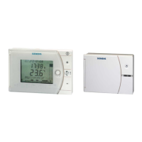
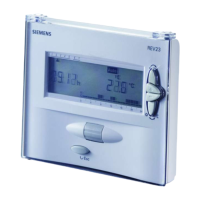
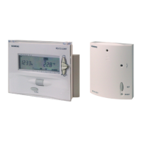
• REV24RF/SET ist ein Apparate-Set bestehend aus
elektronischem Raumtemperaturregler mit Wochenschaltuhr,
Funksender (REV24RF..) und Funkempfänger (RCR10/868)
Mounting notes REV24RF.. and RCR10/868
1 Placement of units
2 Checking the wiring
1.1 REV24RF.. and RCR10/868
For electrical connections, refer to “Connection diagram”.
• The units must be placed such that transmitted and received
signals will be disturbed as little as possible. For this reason,
the following points must be observed with both the
REV24RF.. and RCR10/868:
Note: Do not use stranded wires, only solid wires
or stranded wires with ferrules!
3 Notes
− Do not mount the units on metal surfaces
− Do not mount the units near electrical wires or electronic
equipment such as PCs, TV sets, microwave equipment,
etc.
• The local regulations for electrical installations must be
complied with
• If the reference room is equipped with thermostatic radiator
valves, they must be set to their fully open position
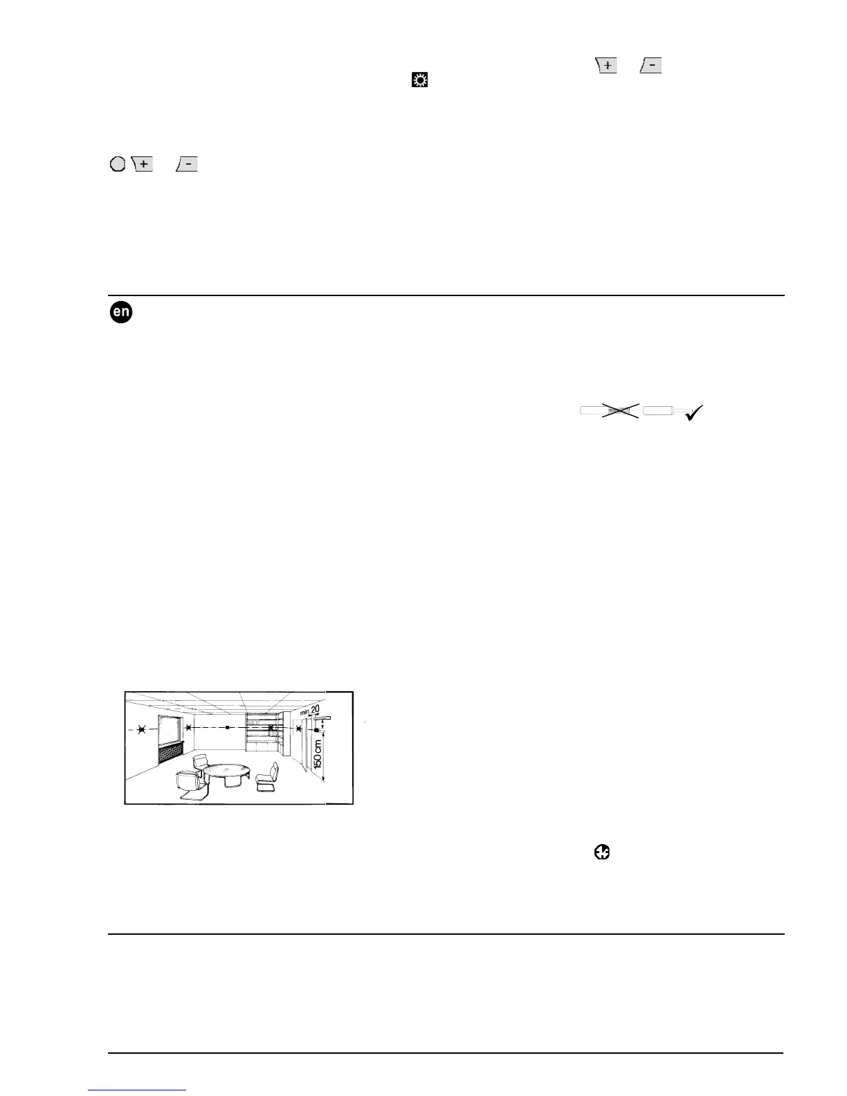
• Do not mount the units in the vicinity of large metal structures
or other construction elements with fine metal meshes like
special glass or special concrete
• If you wish to check the radio link, press the TEST button at
the rear of the REV24RF..
• The distance between controller / transmitter and receiver
must not exceed 20 m or 2 floors
• LED_1 is lit red if the RCR10/868 receives very weak or
corrupted control telegrams, or no control telegrams at all for
about 65 minutes. In this case, check the display of the
REV24RF.. to see if there is an error message
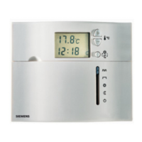
1.2 REV24RF.. (controller / transmitter)
• The controller / transmitter should be mounted in the main
living room (wall mounting according to Fig. C, free standing
according to Fig. E with stand)
•
As long as the RCR10/868 receives control telegrams, the
receiver works normally. If a control telegram is not correctly
received, the relay will maintain the position assumed last.
As soon as the RCR10/868 receives another correct control
telegram from the REV24RF.., the receiver continues to work
normally
• The REV24RF.. must be located such that it can acquire the
room temperature as accurately as possible, without getting
affected by direct solar radiation or other heat or refrigeration
sources
•
If, for 60 minutes, the RCR10/868 receives no control
telegram, or no correct control telegram, the relay will be
deenergized. Hence, the controlled device is switched off.
LED_1 is lit red.
As soon as the RCR10/868 receives another correct control
telegram from the REV24RF.., the receiver continues to work
normally
Wall mounting:
min.
10 cm
2261Z03
• In the event of a power failure at the RCR10/868, the relay is
switched OFF
• Should the REV24RF.. become faulty, the relay of the
RCR10/868 can be controlled manually. As soon as the
REV24RF.. resumes correct operation, its control telegrams
will overwrite the relay’s manual control. This process can take
up to 130 minutes
1.3 RCR10/868 (receiver)
• The receiver and switching unit should preferably be mounted
near the actuating device
•
Press override button to manually energize and
deenergize the relay. LED_1 indicates manual control by
blinking at high frequency. LED_2 is lit when Lx-L1 is closed
(Lx-L2 open). LED_2 is dark when Lx-L1 is open (Lx-L2
closed)
• Make certain that the mounting location is dry and protected
from splash water
• The unit can be fitted to most commercially available recessed
conduit boxes or directly on the wall
Commissioning RF set
1 Switching on the REV24RF..
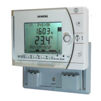
• When starting up, the display shows the type of controller at
top left and “THANK YOU …“ in all available languages on the
text line
• Remove the black battery transit tab (Fig. F); as soon as the
tab is removed, the unit is ready to operate
• Press one of the buttons to stop the running display. The
choice of languages starts with “ENGLISH“ (factory setting).
2 Selecting the language
CE1G2206xx 13.12.2007 7/29