Installation Instructions
11-A-1168-01 Rev. 02
-3--2-
The following instructions are for the installation of a Siemens 3VA branch breaker kit for 250A MAX 3VA52 (MFAS,
HFAS, CFAS), 150A MAX 3VA61 (MDAE, HDAE, CDAE, LDAE) or 250A MAX 3VA62 (MFAE, HFAE, CFAE, LFAE)
breakers in Distribution Switchboards or Type P4 (shallow) / or Type P5 (deep) Panelboards. The parts provided in this
kit are for connections to a 1-phase, 2 or 3-wire system (for the 3VA52 ONLY) or a 3-phase, 3 or 4-wire system. This
kit requires 5” of unit space. The deadfront will need a blank filler plate if this kit does not completely fill the unit space
of any removed branch module(s). For systems without neutrals, disregard the neutral connection.
The breaker is NOT included with this kit and must be purchased separately.
Be sure to choose the appropriate breaker for the system in use.
a. For P4 (Shallow) Panelboards:
The two pins on the bottom of the Top Barrier will
align and insert into bus holes in the A/C bus.
b.
For P5 (Deep) Panelboards or Switchboards:
Fasten the Top Barrier to the B-phase strap using
1/4”-20 x 1/2” screw (Item 8).
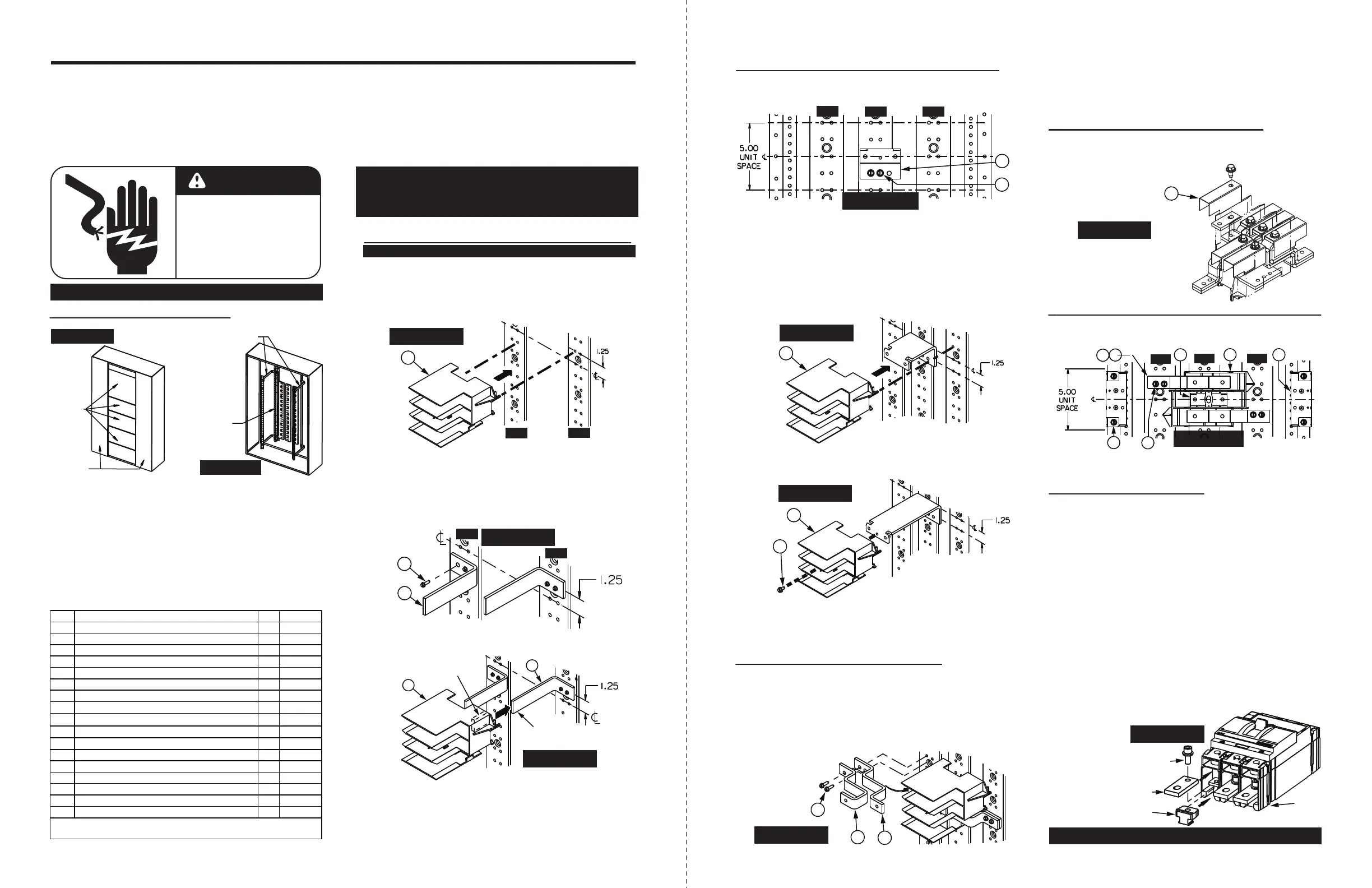
7c. Locate the Top Barrier (Item 4) into the prepared
unit space by centering it in the 5” unit space. Next:
8a. Position one A/C-phase Strap 1 (Item 2) into the unit
space, with the two-hole portion sitting on the A-phase
bus and the single-hole portion set into the A-phase
of the barrier, using the barrier as a fixture. Then
set one A/C-phase Strap 2 (Item 3) on top of Strap 1
(Item 2) aligning the pair of mounting holes on each.
Fasten this pair to the A-phase bus, using two screws
from the Strap-section Bus Hardware Kit (Item 9) of
appropriate length.
8b. Repeat Step 8a to attach a pair of A/C-phase straps
to the C-phase bus.
10a. Locate the Breaker Mounting Brackets (Item 5) on
the Base Rails, and secure them with two pairs of
1/4”-20 x 7/16” screws (Item 7).
2. Remove the (2) gutter covers and cover plates.
3. This kit requires 5” of empty unit space. To locate the
mounting position, measure from the top deadfront
support to the top of the empty unit space filler on the
deadfront. Transfer this dimension from the deadfront
support along the Z-rail and mark. This will be the unit
space as shown on Fig. 11. After marking the Z-rail,
remove the deadfront.
PANELBOARD PREPARATION:
4. If an existing branch module occupies this location,
remove all of its devices, components and parts.
SINGLE-PHASE (1Ø) SYSTEM PREPARATION:
4
Figure 7
4
8
Figure 8
3
AØ
BØ
CØ
2
9
4
5
7
1
A/C-PHASE STRAP PREPARATION:
B
REAKER MOUNTING BRACKET PREPARATION:
11a.
Slide a Nut Keeper (part of Item 15) under each phase
of the breaker stabs on the “ON” side of the breaker.
They “click” into place when properly inserted.
BREAKER PREPARATION:
11b. Place Bus Extension (part of Item 15) on top of each
phase of the breaker stabs, with the smaller and
rounder hole towards the breaker.
11c. Assemble each Bus Extension to each Nut Keeper
with the 5/16”-18 x 3/4” Socket Head Cap Screw
(part of Item 15). (Do not tighten until after breaker
is assembled to the straps.)
SCREW
BUS
EXTENSION
NUT
KEEPER
8c.
Keeping components aligned, tighten all screws to the
torque values specified on the back of the deadfront
(or the table on Page 2).
Figure 12
10b.
Keeping components aligned, tighten all screws to the
torque values specified on the back of the deadfront
(or the table on Page 2).
(CONTINUES ON PAGE 4)
7a.
Fasten the B-phase strap (Item 1) to the B-phase bus,
vertically centered in the 5” unit space, using a pair of
1/4”-20 screws from the Bus Hardware Kit (Item 9).
9a. If a breaker will not be immediately installed, all 3 phases
must get Provision Barriers (Item 17).
Secure them with the
5/16” screw from the Provision Barrier Assembly (Item 17).
Figure 10
7b.
Keeping components aligned, tighten all screws to the
torque values specified on the back of the deadfront
(or the table on Page 2).
6c. Fasten the pair of Top Barrier Supports (Item 12) to
the A/C-phase bus, 1.25” offset from 5“ unit space
centerline, using four 1/4”-20 screws from the Bus
Hardware Kit (Item 9).
UNIT
SPACE
OFFSET
TYP
AØ
CØ
9
12
Figure 4
6d. Each protruding Top Barrier Support bracket end
(Item 12) will fit into a pocket on the bottom of the
Top Barrier (Item 4).
6e.
Keeping components aligned, tighten all screws to the
torque values specified on the back of the deadfront
(or the table on this page).
THREE-PHASE (3Ø) SYSTEM PREPARATION:
7d.
Keeping components aligned, tighten all screws to the
torque values specified on the back of the deadfront
(or the table on Page 2).
1. First, lock off power supplying this equipment.
DANGER
Hazardous voltage.
Will cause death or
serious injury.
Keep out.
Qualified personnel only.
Disconnect and lock off all
power before working on
this equipment.
Figure 1
COVER
PLATES
GUTTER
COVERS
Figure 2
DEADFRONT
SUPPORTS
Z-RAIL
6f. Skip to Step 8a.
For P4 (Shallow) Panelboards:
ONLY allowable for 3VA52 breakers (MFAS, HFAS, CFAS)
6a. Assemble the Top Barrier (Item 4) to the A/C-phase
bus by lining up the two posts at the bottom of the
barrier to the bus holes shown below. (Or reference
Figure 11 on Page 3 for an overhead view.)
6b. Skip to Step 8a.
For P5 (Deep) Panelboards or Switchboards:
4
AØ
CØ
Figure 3
5. Open the shipping box and check the contents:
(refer to bottom of page 1 for KS3VA52T or KS3VA52TD)
*
Deep or shallow components, based on kit
** Deep kits only
B-phase Strap *
1
A/C-phase Strap 1 *
A/C-phase Strap 2 *
Top Barrier
Breaker Mounting Bracket *
5” Cover Plate
2
2
1
2
1
1
2
3
4
5
6
7
1/4”-20 x 7/16” SHWHSW
8
1
8
1/4”-20 x 1/2” SHWHSW **
ITEM
QTY
DESCRIPTION
N/A
N/A
N/A
N/A
TORQUE
N/A
72 lb-in
N/A
9
Strap-section Bus Hardware Kit
1
2
10
11
Card Holder
N/A
Circuit I.D. Card
2
72 lb-in
***
N/A
1Ø Top Barrier Mounting Bracket Kit **
1
Panelboard Branch Neutral Lug Assy.
Breaker Provision Kit
Provision Filler Assembly
2
2
2
2
12
13
14
15
16
17
2
N/A
N/A
N/A
N/A
N/A
N/A
Switchboard Branch Neutral Lug Assy. **
Provision B-phase Barrier
*** 50 lb-in for Aluminum bus; 72 lb-in for Copper bus
“ON”
SIDE OF
BREAKER
1
Figure 6
AØ
BØ
CØ
9
SINGLE-PHASE - Start at Step 6a
THREE-PHASE
- Start at Step 7a
OFFSET
TYP
4
12
POCKET
BRACKET
END
Figure 5
17
NOTE #2: Panels with factory-installed provisions
manufactured before April 2021 did NOT include bus
extensions. When adding a 3VA breaker, kit S3VA52PR
is required, one set per breaker, to complete the install.
9
Figure 9
3
2
NOTE #1: Nut keepers are NOT components of kits
KS3VA52T or KS3VA52TD.
TWIN-MOUNT,
3-PHASE SHOWN
NOTE #3: If breakers are ordered and received with
the nut keepers pre-installed on the “ON” (1,3,5) side,
skip to step 10b.
Figure 11
BREAKER PROVISION PREPARATION:
(refer to pg. 1 for more details about Notes 1 through 3)
(Breakers
ordered with
Nut Keepers
pre-installed
may require
Nut Keeper
removal on
the load end
prior to lug
installation)
 Loading...