Do you have a question about the Siemens SIMATIC PN/J1939 LINK and is the answer not in the manual?
| Product Type | Gateway |
|---|---|
| Product Type Designation | SIMATIC PN/J1939 LINK |
| Protocols Supported | PROFINET, J1939 |
| Power Supply | 24 V DC |
| Mounting Type | DIN rail |
| Degree of Protection | IP20 |
| Weight | Approx. 200 g |
| J1939 Interface | 1 x 9-pin D-Sub |
| PROFINET Interface | 2 x RJ45 |
Purpose of the document and target audience.
Lists the necessary knowledge for understanding the operating instructions.
Lists supplementary documents and their availability.
General safety advice, including CAUTION notice and warnings.
Details safety requirements for extra-low voltage connections and working on the device.
Discusses industrial security and cyber threat prevention measures.
States that only authorized personnel can access and modify the system.
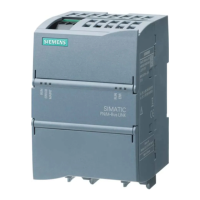
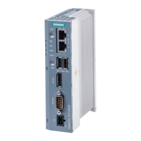
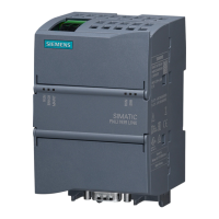
Describes the PN/J1939 LINK as a gateway between PROFINET and J1939 networks.
Lists general characteristics, J1939 features, and configuration limits.
Shows a basic system configuration and explains component functions.
Lists hardware and software requirements for the PN/J1939 LINK.
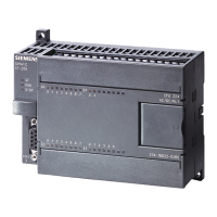
Details the physical design and labeling of the PN/J1939 LINK.
Explains the Extended CAN format and 29-bit message ID structure.
Describes the address space and available addresses for J1939 devices.
Details the composition and information within the 64-bit J1939 device name.
Explains the J1939 address assignment procedure and device name behavior.
Details BAM and CMDT transport protocols for data volumes larger than 8 bytes.
Explains how J1939 ECUs report diagnostic trouble codes using DM messages.
Overview of PGN parameters configurable in TIA Portal via GSDML file.
Explains communication paths for cyclic and acyclic data exchange.
Defines the "OFF" and "ON" states of the PN/J1939 LINK.
Provides details on control and status information exchanged with the S7 controller.
Explains diagnostic resources and behavior during communication failures.
Provides instructions for mounting the PN/J1939 LINK on a mounting rail or control panel.
Step-by-step guide for mounting the device onto a standard mounting rail.
Step-by-step guide for mounting the device onto a control panel.
Safety information and guidelines for connecting the device.
Guidelines for cable routing, grounding, and strain relief for EMC.
Explains electrical isolation and shielding principles of the PN/J1939 LINK.
Details the connection of the external 24 V DC power supply.
Instructions for connecting the functional ground for EMI discharge.
Guides on connecting PROFINET using Ethernet cables and connectors.
Instructions for connecting the PN/J1939 LINK to the J1939 network via DSUB connector.
Outlines prerequisites and basic procedure for commissioning the device.
Step-by-step guide for commissioning using the TIA Portal.
Outlines the essential work procedure for configuring the PN/J1939 LINK in TIA Portal.
Details how to integrate and configure the device in the TIA Portal's hardware catalog.
Explains how to configure module parameters for the J1939 LINK.
Details the parameter values forming the 64-bit device name and their function.
Describes how to insert and configure pre-defined parameter groups.
Details setting PGN parameters for input modules.
Details setting PGN parameters for output modules, including fragmentation.
Explains selecting and configuring PGN input proxies for acyclic data reading.
Explains selecting and configuring PGN output proxies for acyclic data writing.
Explains how to check configuration consistency by compiling.
Explains setting control information via S7 user program for data transfer.
Explains the status LEDs for visualizing operating states.
Details the LEDs for visualizing operating states of the device and PROFINET ports.
Explains the LEDs indicating connection status of Ethernet interfaces.
Explains the J1939 bus status indicated by LEDs.
Details diagnostic messages sent to the S7 controller.
Lists events that trigger diagnostic messages and their removal events.
Provides a table of diagnostic messages, causes, and solutions.
Procedure for updating the firmware of the PN/J1939 LINK.
Basic steps required for replacing the PN/J1939 LINK.
Information on recycling and disposal of the PN/J1939 LINK.
Comprehensive technical specifications of the PN/J1939 LINK.
Details voltage supply type, rated value, range, and protections.
Lists interface types, supported protocols, and port details.
Specifies CAN operating modes and transmission rates.
Lists J1939 addressable ECUs, logical nodes, and supported data types.
Lists various certifications like CE, UL, EAC, PNO.
Visual representation of the device's dimensions in millimeters.
Lists certifications and approvals, including CE marking and EMC directives.
Provides the contact address for Siemens AG and other applied standards.
Discusses the use of open source software and license conditions.
Information on obtaining technical support and online services.
Provides contact details for technical support in Germany and other countries.
Information on accessing Siemens Industry Online Support portal for services.
Procedure for claiming an address in the network.
S7 connection for data exchange in PROFINET.
Transport protocol for broadcasting data to bus nodes.
Software of an ECU, potentially containing multiple CAs.
Serial bus system belonging to the fieldbus family.
Language for describing PROFINET IO field devices.
Number used to uniquely identify a parameter group.
Open Industrial Ethernet standard for automation.