PROFIBUS DP
5.1 CPU 41x-3 PN/DP as DP master / DP slave
S7-400 Automation System, CPU Specifications
Manual, 10/2006, 6ES7498-8AA04-8BA0
5-19
Evaluation in the User Program
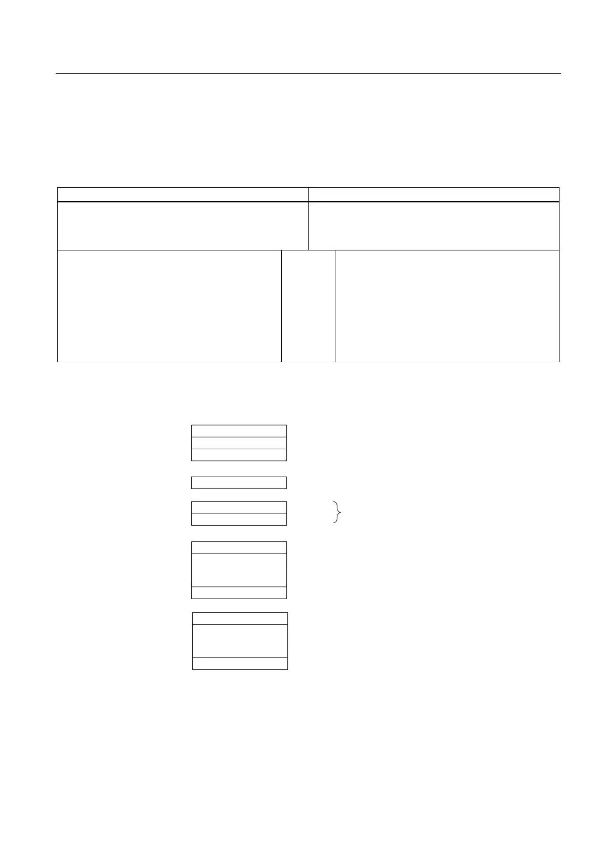
The table below shows an example of you how you can evaluate RUN-STOP transitions of
the DP master in the DP slave (see also the previous table).
Table 5-13 Evaluating RUNSTOP transitions in the DP Master/DP Slave
In the DP master In the DP slave (CPU 41x)
Diagnostic addresses: (example)
Master diagnostic address=1023
Slave diagnostic address
in the master system=1022
Diagnostic addresses: (example)
Slave diagnostic address=422
Master diagnostic address=not relevant
CPU: RUN → STOP The CPU calls OB82 with the following information,
amongst other things:
• OB82_MDL_ADDR:=422
• OB82_EV_CLASS:=B#16#39
(incoming event)
• OB82_MDL_DEFECT:=module
malfunction
Tip: The CPU diagnostic buffer also contains this
information
Structure of Slave Diagnostics
Byte 0
Byte 1
Byte 2
Byte 3
Byte 4
Byte 5 Low byte
High byte
Byte 6
Byte x
.
.
.
.
.
.
Byte x+1
Byte y
Station statuses 1 to 3
Master PROFIBUS address
Manufacturer ID
Module diagnostics
(The length depends on the number of
configured address areas in the intermediate
memory1)
(The length depends on the number of configured
address areas in the intermediate memory)
Station diagnosis
1) Exception: In the case of invalid configuration of the DP master, the DP slave interpretes 35 configured address areas (46H).
to
to
Figure 5-3 Structure of slave diagnostics

 Loading...


