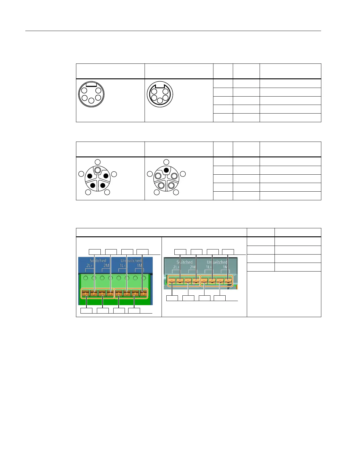
7/8" connector
X01 - 24 V power supply
(IN), 5-pin, male
X02 - 24 V power supply
(OUT), 5-pin, female
Pin Signal Description
1 2M Switched 0 V
2 1M Unswitched 0 V
3 FE Not connected
4 1L+ Unswitched 24 V
5 2L+ Switched 24 V
M12 L-coding connector
X01 - 24 V power supply
(IN), 5-pin, male
X02 - 24 V power supply
(OUT), 5-pin, female
Pin Signal Description
1 1L+ Unswitched 24 V
2 2M Switched 0 V
3 1M Unswitched 0 V
4 2L+ Switched 24 V
- FE Not connected
Glanded variant
X01/X02 - 24V power supply terminals Signal Description
Motor-mounted converter
/0
/
0
/0
/
0
,1
287
Wall-mounted converter
/0
/
0
/0
/
0
,1
287
2L+ Switched 24 V
2M Switched 0 V
1L+ Unswitched 24 V
1M Unswitched 0 V
Cable gland size: M20* 1.5
Switched/unswitched 24V power supply
The unswitched (also known as "non-switched") 24 V power supply (1L+) is required for the drive
to function.
• Use a power supply with PELV (Protective Extra Low Voltage).
• The 0 V of the power supply must be connected with low resistance to the PE of the system.
The switched 24 V (2L+) supplies the two bidirectional digital inputs/outputs DIO 24 and DIO
25. Switching o the 24 V power supply voltage brings all of the actuators connected to the
digital outputs into the no-voltage state.
If you don't need the switching of 2L+ power supply, you can connect the conductors 2M
(switched 0 V) to 1M (unswitched 0 V) and 2L+ (switched 24 V) to 1L+ (unswitched 24 V)
Wiring
5.11Connecting the 24 V power supply
SINAMICS G115D Wall Mounted distributed drive
78 Operating Instructions, 07/2023, FW V4.7 SP14, A5E52808211A AA

 Loading...


