Procedure
1. Position the cursor at the kinematic chain element to which you wish to
attach a protection area.
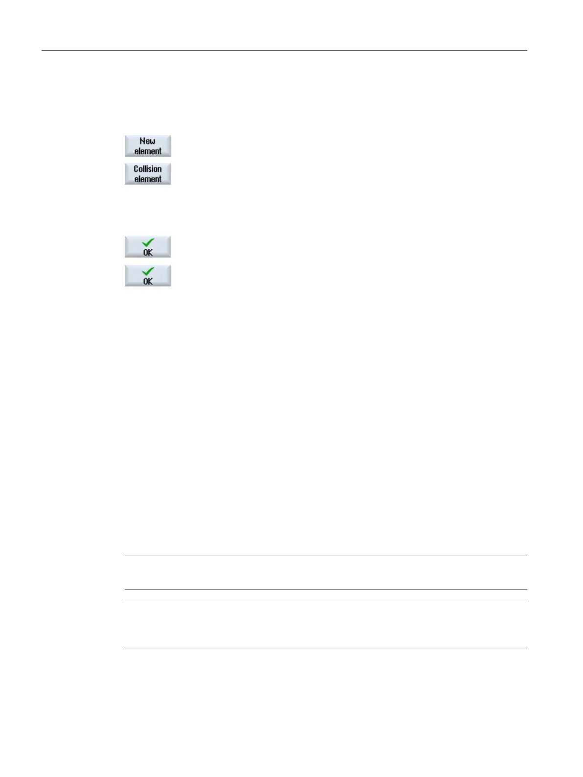
2. Press the "New element" softkey.
3. Press the "Collision element" softkey.
The "New Collision Element" selection window opens.
4. Select "Machine protection area" if you wish to model a machine part.
- OR -
Select "Tool protection area" if you wish to model a tool part.
5. Press the "OK" softkey to insert the element.
The "Machine Protection Area" or "Tool Protection Area" window opens.
6. Enter the desired values and press the "OK" softkey to confirm your en‐
tries.
Attach additional protection areas
You have the option of attaching as many protection areas as you require,
corresponding to your machine.
See also
Tool protection area (Page 304)
Machine protection area (Page 305)
14.7.2.2 Tool protection area
Parameterize model use in the "Tool Protection Area" window.
You determine from where the controller gets the data for creating the machine model.
Further, you define the parameters to monitor and display the element.
For a protection area, the protection area element is automatically taken from the tool
management data. For instance, if you define a tool protection area for a tool in the spindle,
then for a tool change (M6), a new tool protection area element is created with the data of the
new tool.
Note
For the automatic tool protection area, a spindle must exist in the channel.
Note
Attaching a tool protection area
"Frame" type tool protection area elements may be attached to tool protection areas.
Collision avoidance
14.7 Creating a kinematic structure
SINUMERIK Operate (IM9)
304 Commissioning Manual, 12/2017, 6FC5397-1DP40-6BA1

 Loading...


