OPERATION
When control box is turned on and all buttons are depressed,
the R.A. motor will rotate at the proper speed to compensate
for the earth's rotation. The declination axis does not
automatically rotate. For proper polar-aligned observing,
no corrections are needed to the declination axis to track
celestial objects. The speed of the declination motor is
simultaneously controlled by the 2X/4X/8X control box
switch.
The shaft gear assembly operates as a friction clutch to allow
disengagement of the motor drive. To use the declination
fine-adjust cable, loosen the knurled wheel on the shaft gear
to disengage motor. Tighten wheel to engage motor again.
The declination axis locking knob can be loosened for slewing
without having to disengage motor gear first.When the power
is on and all buttons on the control box are depressed,
The N/Off/S switch acts as a power switch as well controlling
direction of clock drive. The "N" position allows R.A. motor
to track for Northern Hemisphere observing and the "S"
position is suitable for the Southern Hemisphere. The
2X/4X/8X switch changes rotation speed used by the control
box buttons. It sets rotation rate for multiple of tracking speed.
The up-down buttons control the declination motor while the
left-right buttons change the R.A. axis.
The right "2X"button will rotate the telescope forward at
twice the tracking speed or approxiamately ½º per minute.
The left "2X" button stops all motion and allows stars to drift
by at their normal rotation rate of approx. ¼º per minute.
The "8X" buttons allows forward at eight times the tracking
rate (approx. 2º per minute) and the reverse button move the
telescope backwards at seven times the tracking rate
(approx. 1 ¾º per minute).
The tracking speed of the R.A. motor is factory set and
should not need adjustment. Adjustment of the variable
resistor inside the control box should be preformed by an
experienced technician
It may be necessary to loosen the worm gear for the R.A. or
declination axis to allow a the motor drive to rotate freely.
The interface for the worm gear is located inside the rectangular
section which the fine-adjust cables are attached. The worm
gears are held in place by two pairs of 5mm hex screws located
behind and below the rectangular section. The bottom two
hex screws will have a 2mm set screw between them.
Carefully loosen all four screws a small amount. Loosen the
2mm set screw about ¼ turn. Re-tighten the four hex screws
holding the worm gear in place. If the worm gear assembly
is too loose, excess backlash will be detected in the motor
gears. It will be necessary to tighten the worm gear set screw
about a ¼ turn.
0
10
20
30
40
50
60
70
80
90
10.
11.
13.
12.
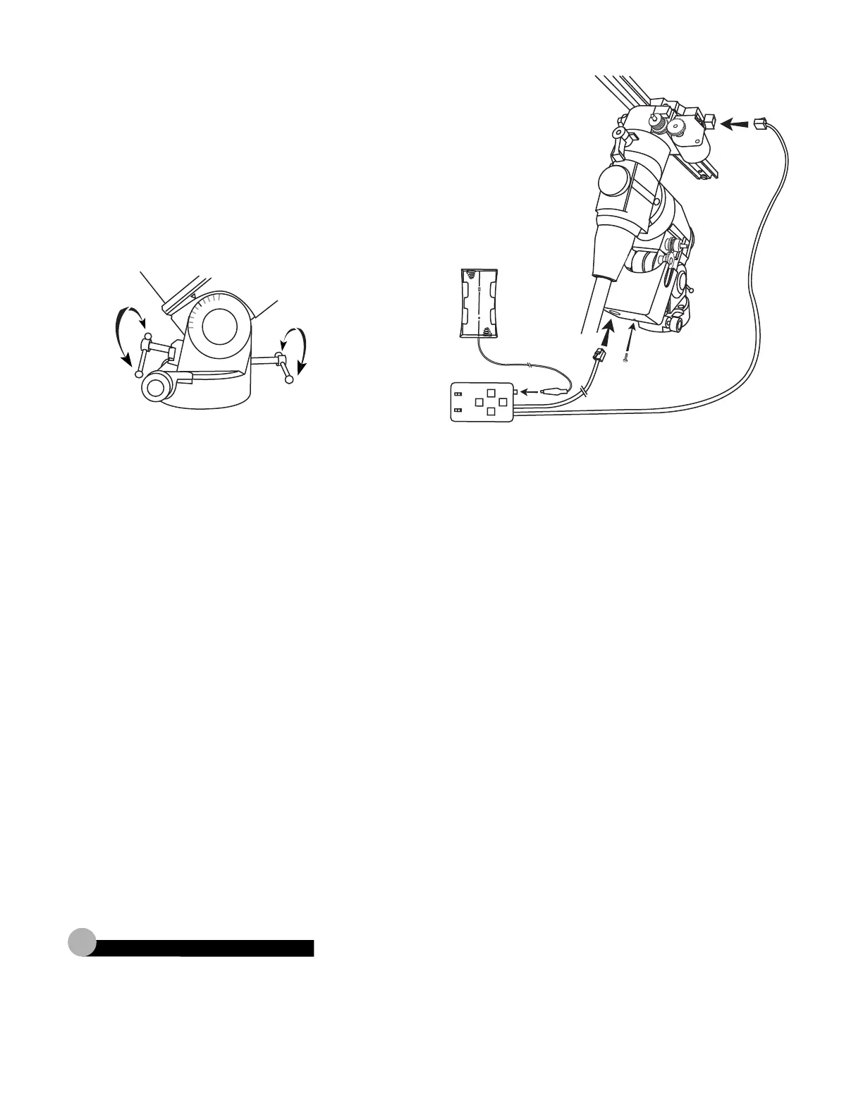
DEC MOTOR INSTALLATION (continued)
10) Turn the altitude adjustment knob until the latitude scale indicates 50º.
11) Replace plastic cover and secure with small phillips screw.
Remove oval tab from side cover to allow space for the shaft gear assembly.
12) Plug R.A. and DEC cords from control box into appropriate RJ-11 jacks on
electric motors.
13) Plug DC power cord from battery case into control box.
2
Canada: 604-270-2813 between 9:00AM and 3:00PM PST
Outside Canada: Please contact your dealer for technical support.
T
echnical Support
 Loading...