EX500-TF2Z176EN
Page 1 of 2
Instruction Manual
Gateway unit – EtherNet/IP
TM
compatible
Series EX500-GEN2
The intended use of the Gateway unit is for connection to SI units and
input devices for the control of pneumatic valves.
1 Safety Instructions
These safety instructions are intended to prevent hazardous situations
and/or equipment damage. These instructions indicate the level of
potential hazard with the labels of “Caution,” “Warning” or “Danger.”
They are all important notes for safety and must be followed in addition
to International Standards (ISO/IEC)
*1)
, and other safety regulations.
*1)
ISO 4414: Pneumatic fluid power - General rules relating to systems.
ISO 4413: Hydraulic fluid power - General rules relating to systems.
IEC 60204-1: Safety of machinery - Electrical equipment of machines.
(Part 1: General requirements)
ISO 10218-1: Manipulating industrial robots -Safety. etc.
• Refer to product catalogue, Operation Manual and Handling
Precautions for SMC Products for additional information.
• Keep this manual in a safe place for future reference.
Caution indicates a hazard with a low level of risk which, if
not avoided, could result in minor or moderate injury.
Warning indicates a hazard with a medium level of risk
which, if not avoided, could result in death or serious injury.
Danger indicates a hazard with a high level of risk which, if
not avoided, will result in death or serious injury.
Warning
• Always ensure compliance with relevant safety laws and
standards.
• All work must be carried out in a safe manner by a qualified person in
compliance with applicable national regulations.
• Refer to the operation manual on the SMC website (URL:
https://www.smcworld.com) for more Safety instructions.
2 Specifications
General specifications
Ambient operating temperature
35 to 85% RH (no condensate)
Ambient storage temperature
1000 VAC applied for 1 minute
Electrical specifications
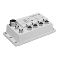
3 Name and function of parts
Connection to EtherNet/IP
TM
line.
Connection for power supply.
Connection to SI units (with manifold
valves) or input units using a branch
cable.
Displays the unit status.
Switches for setting address, etc.
4 Installation
4.1 Direct mounting
Secure in position using 4 x M5 screws, 15 mm minimum thread length.
4.2 Wiring connections
• Communication Connector
Select the appropriate Ethernet cables to mate with the connectors
on the SI unit. The EtherNet/IP connection has 2 ports, PORT 1 and
PORT 2, and both ports can be used for connection.
M12 4-pin Socket (D-coded)
Pin No. Signal name
• Power Supply Connector
Connect the power supply to the power supply connector on the
Gateway unit. With this cable, power is supplied to the output devices
(such as solenoid valve) and the input devices and for control.
• Both single and two power supply systems can be adopted, however
the wiring should be made separately (for solenoid valves / outputs
and for input and control) for either system.
The M12 connector cable has two types, Sta
SPEEDCON compatible. If both plug and socket have SPEEDCON
connectors, the cable can be inserted and connected by turning it a
1/2 rotation.
A standard connector can be connected to a SPEEDCON connector.
• Branch Connector
Connect SI units (solenoid valves) and input devices to the Branch
port connectors (COM A - D) using an M12 (8-pin) connector cable
(EX500-AC###-S#P#).
As each cable contains power supply wiring, there is no need to
supply power to the SI unit (solenoid valves) or input devices
separately.
Warning
• Be sure to fit a seal cap (EX9-AWTS) on any unused connectors.
Proper use of the seal cap enables the enclosure to maintain IP65
specification. Tightening torque: 0.1 N•m.
4.3 Ground Connection
• Connect the FE terminal (M3) to ground.
• Individual grounding should be provided close to the product with a
short cable to assure the safety and noise resistance of the system.
• Resistance to ground should be 100 Ω or less.
4 Installation (continued)
4.4 Environment
Warning
• Do not use in an environment where corrosive gases, chemicals, salt
water or steam are present.
• Do not install in a location subject to vibration or impact in excess of
the product’s specifications.
• Do not mount in a location exposed to radiant heat that would result
in temperatures in excess of the product’s specifications.
5 Setting
5.1 Switch setting
• Open the switch cover to set the switches using a small flat blade
screwdriver.
• The power supply should be turned OFF while setting the switches.
• Whenever the switch cover has been opened, close the cover and
tighten the screws to the specified tightening torque.
Recommended tightening torque: 0.6 N•m.
5.2 IP address setting
5.3 DIP switch setting
Description
1 Reserved (fixed to OFF).
2
ON: If EtherNet/IP communication error occurs, the output
will be retained.
OFF: Set the output condition during EtherNet/IP error via
network. Cleared when this is not set.
3
ON: Gateway distribution setting (64 points).
OFF: Gateway distribution setting 2 (128 points).
4
Manual setting of IP address: 192.168.Y.X
(Y: OFF_0, ON_1)
The default setting is OFF.
*1: Remote control
The mode to respond to the commands below of BOOTP/DHCP
Server provided by Rockwell Automation.
Enable DHCP
Information including IP address can be obtained from
BOOTP/DHCP Server. If the power is supplied again in this state,
EX500 tries to obtain the information including IP address again.
Disable BOOTP/DHCP
Information including IP address is not obtained from BOOTP/DHCP
Server. Previous setting can be held if power is supplied under this
condition.
*2: Manual setting of IP address
IP address is set within the range of 192.168.0.1 to 192.168.0.254,
192.168.1.1 to 192.168.1.254.
*3: DHCP mode
Obtain IP address from DHCP Server. Obtained IP address is lost
when power supply is cut.
Default setting
"Enable DHCP" at "Remote control".
Power supply voltage
Control and Input: 24.0 VDC ±10%
Solenoid valves: 24.0 VDC +10% / -5%
Rated Current
Power supply for control and input: 6.2 A
(GW current consumption: 200 mA max.).
Power supply for solenoid valve: 4 A
Number of Inputs / Outputs
Communication specifications
100BASE-TX (CAT5 or more)
10/100 Mbps (Automatically selected)
Communication method
Full duplex / half duplex (autumatically
selected)
I/O Message
Input: 20 bytes (assembly instance: 100)
Output: 20 bytes (assembly instance: 150)
IP address setting range
Setting of specified address by DHCP
server or internal switch.
(192.168.0.1 to 192.168.0.254, 192.168.1.1
Device information
Product type: 12 (Communication adapter)
Applicable function
DLR
Web server (Applicable browser: Internet
Explorer6 to 11, Firefox28.0 to 31.0,
Google Chrome 36.0 to 37.0)
Low level bus specifications
Number of inputs / outputs
Gateway distribution system 2 (128 point)
Number of branch ports
4 (input: Max. 32 points / Output: Max. 32
points per branch)
Number of connected slaves
16 max. (input unit: 2 pcs. / SI unit: 2 pcs.
per branch)
Power supply for control and input
24 VDC, Max. 1.5 A per one branch port
Power supply for Solenoid valve
24 VDC, Max. 1.0 A per one branch port
Total length 20 m or less per branch
24 VDC (control and input)
4 0 V (solenoid valves)
Description
Manual setting of IP address:
192.168.Y.X
(X = 1-254)
*2
Reserved
The default setting is 0.