Installation and Maintenance Manual
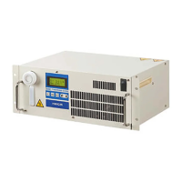
Water Cooled Thermo Con for Rack Mount
HECR Series
Original Instructions
1 Read Before Using
Thank you for purchasing SMC’s Thermo-con (hereinafter referred to as
the “product”). This “Installation and Maintenance Manual” (hereinafter
referred to as “this manual”) briefly explains the essential safety instruction
procedures to start and stop the product and reset its alarms. Read this
manual before using.
2 Safety Instructions
This manual contains essential information for the protection of users and
others from possible injury and/or equipment damage.
Read this manual before using the product, to ensure correct handling,
and read the manuals of related apparatus before use.
Keep this manual in a safe place for future reference.
These instructions indicate the level of potential hazard by label of
“Caution”, “Warning” or “Danger”, followed by important safety
information which must be carefully followed.
To ensure safety of personnel and equipment the safety instructions in
this manual and the product catalogue must be observed, along with
other relevant safety practices.
If instructions are not followed there is a
possibility of injury or equipment damage.
If instructions are not followed there is a
possibility of serious injury or loss of life.
In extreme conditions, there is a possibility of
serious injury or loss of life.
This manual provides the following symbols in addition to “Danger”,
“Warning”, and “Caution” to present warning details in an easy-to-
understand manner.
This symbol warns you of potential electrical shock.
This symbol warns you of potential burns.
During operation or maintenance of the product, do not disable the
interlock function of any device. Otherwise unexpected personnel injury
or damage to the product may occur.
When turning on/off the power observe the procedure. Otherwise
unexpected malfunction or danger may occur.
When maintaining, cleaning or in case of emergency, turn off the power
source.
After identifying a problem be sure to check the cause and take
necessary countermeasures before turning on the power.
The product is operated at high voltage.
The compatibility of equipment is the responsibility of the person
who designs the system or decides its specifications.
Since the products specified here can be used in various operating
conditions, their compatibility with the specific system must be based on
specifications or after analysis and/or tests to meet specific requirements.
Only trained personnel should handle or operate the product.
Transportation, installation and maintenance of the product can be
dangerous and should be done by persons who have full knowledge and
experience on the product and system. Cover panels of the product should
be opened only by qualified service technicians or qualified personnel.
Do not modify or reconstruct the unit.
Read all warning and caution labels carefully and keep them in mind.
Do not peel off or rub alert warning and caution labels. Confirm locations
of alert warning and caution labels.
Do not service machinery/equipment or attempt to remove
components until safety is confirmed.
2 Safety Instructions Continued
1) Inspection and maintenance of machinery/equipment should only be
performed after confirmation of safe locked-out positions.
2) When equipment is to be removed, confirm the safety process as
mentioned above. Switch off electrical supplies and ensure any high
temperature parts have cooled to ambient temperature.
3) Before machinery/equipment is re-started, ensure all safety measures
are taken so the product and system can be started in a safe manner.
4) Do not use this product outdoor (indoor use).
Do not use this product outside of the specifications. Contact SMC
if it is to be used in any of the following conditions.
1) Conditions and environments beyond the given specifications.
2) Installations in conjunction with atomic energy, railway, air navigation,
vehicles, medical equipment, food and beverage, recreation equipment,
emergency stop circuits, press applications, or safety equipment.
If abnormal conditions occur, such as abnormal noise or smoke, or water
leakage, take the following actions。
1) Shut down power.
2) Contact an authorised SMC dealer for repair.
After shutting down the power supply, ensure a time interval at least
3sec between ON and OFF. Restarting the product within that interval
may cause it to malfunction.
Do not use devices that generate electromagnetic radiation such as
cellular phones near the product. There is a possibility that this can
cause the product to malfunction.
This unit has several interlock functions, which activate when a dangerous
operation or condition occurs to stop the product and make it safe. This is
a function to protect personnel and restrict operation that may cause
damage to the product or facility, and to remove dangers related to safety.
When dispose the product, contact an industrial waste disposal
company for disposal of the product. To minimize the risk, drain the fluid
from the product when it is scrapped. If the fluid is left inside, an accident
and damage can result during transportation.
3 Specifications
3.1 General Description and Intended Use
This product uses a built in pump to circulate liquid (water or 20% EG) at a
constant temperature, controlled by Thermo-Electric (Peltier) Modules. This
circulating fluid cools parts of the customer’s machine that generates heat.
3.2 General Specifications
10.0 to 60.0 C (No dew condensation)
Temp: 10 to 35 C
Humidity : 35 to 80%RH
Altitude : up to 1000m
Environment : No corrosive gas, solvent such as thinner and flammable gas
Temp :-40 to 70 C (No dew condensation and icing)
Humidity : 5 to 95%RH
Environment : No corrosive gas, solvent such as thinner and flammable gas
Indication accuracy: +/- 0.2 C.
Temperature drift: +/- 0.2C
Stability: +/- 0.01 to 0.03 C
(Circulating fluid OUT is directly connected with IN)
Cooling capacity
(Set Temp. 20C and Facility
water Temp. 20C, 10L/min)
Approx. 800W
(Circulating fluid flow rate 3L/min)
Approx. 1200W
(Circulating fluid flow rate 3L/min)
Water, Ethylene glycol solution up to 20%
Refer to performance chart.
IN/OUT: Rc3/8 , Drain: CPC PLCD16004
Stainless steel, EPDM, NBR, Ceramic, PPE, PPS, Carbon, Polyethylene, POM
Single phase AC100 to 240V(+/- 10%),
50/60Hz
Single phase AC200 to 240V(
+/- 10%
),
50/60Hz
Max.10A(100V)
Max.4A(240V)
Max.7A (200V)
Max.6A (240V)
Limitation of hazardous
substance
3 Specifications Continued
Auto tuning, Off set function, Learning control function, External tuning control function,
Temperature sensor fine control function, Setting value memory function, Upper / lower
temperature limit alarm function, Output shut off alarm, Communication,
Input operation and
indications
Membrane key sheet
LCD display panel (with back light)
Output shut off alarm,
Upper / lower temperature limit alarm : Relay contact specification
DC30V, 2A (Resistance load)
DC30V, 1A (Induction load)
RS-232C / RS-485
Communications:
Setting of target temperature, Reading of the value detected by temperature sensor,
Reading of warning status, Setting and of off-set value, Setting and reading of control
operation, Setting and reading of PID values, Reading of output ratio.
For operation by communication, it is necessary to order
“Communication Manual”.
Use shielded cable for serial communications.
Resistance thermometer sensor (Pt100, 3-wire, class A, 1mA)
(Both internal sensor and external sensor)
With flow switch: Low flow rate alarm occurs at less than 0.7L/min
NPT fitting: Fluid IN/OUT fittings
With foot and no rack bracket
High head pump
Thermo-con 1pc
Installation and Maintenance Manual 1pc
Power supply connector 1pc
3.3 Performance Charts
Values on the performance charts are not guaranteed values but
representative values. Allow margins for safety when selecting the model.
3.3.1 Cooling Capacity
HECR008-W
0
500
1000
1500
2000
2500
0 10 20 30 40 50 60 70
Circulating f luid temp. deg.C
Facility water temp. 10deg.C
Facility water temp. 35deg.C
Facility water temp. 20deg.C
Circulating f luid:Water
Circulating f luid flow rate:3L/min
Facility water flow rate:10L/min
0
500
1000
1500
2000
2500
0 10 20 30 40 50 60 70
Circulating f luid temp. deg.C
Facility water temp. 20deg.C
Circulating f luid: Ethylene glycol 20%
Circulating fluid flow rate:3L/min
Facility water flow rate:10L/min
*Cooling capacity decrease about 50W when high head pump option selected.
HECR012-W
0
500
1000
1500
2000
2500
3000
0 10 20 30 40 50 60 70
Circulating f luid temp. deg.C
Facility water temp. 10deg.C
Facility water temp. 20deg.C
Facility water temp. 35deg.C
Circulating fluid:Water
Circulating f luid flow rate:3L/min
Facility water flo w rate:10L/min
0
500
1000
1500
2000
2500
3000
0 10 20 30 40 50 60 70
Circulating fluid temp. deg.C
Facility water temp. 20deg.C
Circulating f luid:Ethylene glycol 20%
Circulating f luid flow rate:3L/min
Facility water flow rate:10L/min
*Cooling capacity decrease about 50W when high head pump option selected.
3.3.2 Heating Capacity
HECR008-W
0
500
1000
1500
2000
2500
0 10 20 30 40 50 60 70
Circulating f luid temp. deg.C
Facility water temp. 35deg.C
Facility water temp. 20deg.C
Facility water temp. 10deg.C
Circulating f luid:Water
Circulating f luid flow rate:3L/min
Facility water flow rate:10L/min
0
500
1000
1500
2000
2500
0 10 20 30 40 50 60 70
Circulating f luid temp. deg.C
Facility water temp. 20deg.C
Circulating f luid: Ethylene glycol 20%
Circulating f luid flow rate:3L/min
Facility water flow rate:10L/min
3 Specifications Continued
HECR012-W
0
500
1000
1500
2000
2500
3000
0 10 20 30 40 50 60 70
Circulating f luid temp. deg.C
Facility water temp. 10deg.C
Facility water temp. 35deg.C
Facility water temp. 20deg.C
Circulating f luid: Water
Circulating fluid flow rate:3L/min
Facility water flow rate:10L/min
0
500
1000
1500
2000
2500
3000
0 10 20 30 40 50 60 70
Circulating f luid temp. deg.C
Facility water temp. 20deg.C
Circulating f luid:Ethylene glycol 20%
Circulating f luid flow rate:3L/min
Facility water flow rate:10L/min
3.3.3 Pump Capacity
HECR008/012-W
0.00
0.02
0.04
0.06
0.08
0.10
0.12
0.14
0.16
0.18
0.0 1.0 2.0 3.0 4.0 5.0
Circulating f luid flow rate L/min
0.00
0.05
0.10
0.15
0.20
0.25
0.30
0.35
0.0 1.0 2.0 3.0 4.0 5.0 6.0 7.0
Circulating fluid flow rate L/min
3.3.4 Pressure Loss in Facility Water Circuit
HECR008-W HECR012-W
0.00
0.02
0.04
0.06
0.08
0.10
0 5 10 15 20
Facility water flow rate L/min
0.00
0.02
0.04
0.06
0.08
0.10
0 5 10 15 20
Facility water flow rate L/min
3.4 Connector Specifications
Power supply
connector
(IEC60320,C14)
Communication
connector
Note: Always
use shielded
cable connected
to this connector.
5 4 3 2 1
9 8 7 6
D-sub 9 pin (socket type)
Fixed screw: M2.6
Signal・
External
temperature
sensor
connector
Note: Always
use shielded
cable connected
to this connector.
8 1
15 9
D-sub 15 pin (Socket type)
Fixed screw: M2.6
Output Cutoff Alarm a contact
(OPEN During Alarm)
Output Cutoff Alarm Common
Output Cutoff Alarm b contact
(CLOSE During Alarm)
Temperature Alarm a contact
(OPEN During Alarm)
Temperature Alarm b contact
(CLOSE During Alarm)
HEC-OM-U015
First edition : 2017. Oct
When high head pump option selected