NL
E
5
4
3
2
1
6
7
8
9
Connection diagram of
resistance temperature sensor
8
7
6
5
4
3
2
1
9
10
11
12
13
14
15
5
4
3
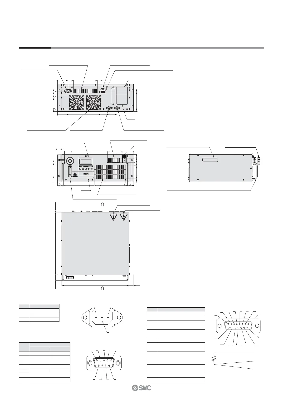
Air
Air
Ventilation hole (air inlet)
Display/Operation panel
Ventilation hole (air inlet)
Circulating water level gauge
Label
Tank lid (with gasket)
Fluid fill port
Handle (for installing/removing the product to/from the rack)
Handle (for carrying the product)
Power supply connector
Ventilation hole (air outlet) Communication connector
External temperature sensor connector
Alarm output connector
Model no. label
Ventilation hole (air outlet) Circulating fluid outlet
Rc 3/8
Circulating fluid inlet
(Circulating fluid drain port)
Rc 3/8
Label
Caution label/Electricity
Warning/Caution label
Power switch
447
38
474.5
9.5
484
250
0
49
7
134
139.7
0
38
151
176
107
125
139.7
38
0
21
0
166
84
403
144
0
10
69
289
256
0
104
144
124
0
23
278
331
381
0
75
129
118
105
(10)400(33)
430 27
10
Dimensions
HECR004-A5
1. Power supply connector
IEC60320 C14 (or equivalent)
Pin no.
Signal contents
N 100-240 V AC
L 100-240 V AC
E PE
2. Communication connector
D-sub 9 pin (socket)
Holding screw: M2.6
Pin no.
Signal contents
RS-232C RS-485
1 Unused BUS+
2 RD Unused
3 SD Unused
4 Unused Unused
5 SG SG
6-8 Unused Unused
9 Unused BUS–
3.
External temperature sensor connector/Alarm output connector
D-sub 15 pin (socket)
Holding screw: M2.6
Pin no.
Signal contents
1-2 Unused
3
Terminal A of resistance temperature detector
4
Terminal B of resistance temperature detector
5
Terminal B of resistance temperature detector
6
Contact a for output cutoff alarm
(open when alarm occurs)
7
Common for output cutoff alarm
8
Contact b for output cutoff alarm
(closed when alarm occurs)
9
Contact a for upper/lower temp. limit alarm
(open when alarm occurs)
10
Common for upper/lower temp. limit alarm
11
Contact b for upper/lower temp. limit alarm
(closed when alarm occurs)
12-14 Unused
15 FG
15
Series HECR
 Loading...