19
EN
ATYSp - 542001E - SOCOMEC
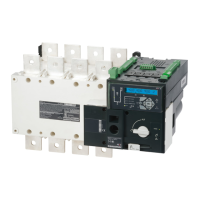
STEP 7C
Manual Mode
AUT
90°
90°
II
I
0
Ensure that the emergency handle is
not inserted in the product and turn
the mode selector to the AUT position.
LED “Power” Green: ON
LED Manuel/Default: OFF
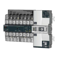
STEP 7A
AUT Mode
(AutomaticControl)
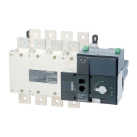
STEP 7B
AUT Mode
(RemoteControl)
To enable control, close contact 312 with 317.
For contactor logic bridge contact 316 with 317.
To operate: close the contact corresponding to
the desired position.
To force the product to 0 position “OFF” bridge
contact 313 with 317.
Imp.≥60ms maintened
order I
position I
order 0
position 0
order II
position II
Contactor logicImpulse logic
POWER
AUT
Ø 4 ... 8mm
PROG
OK
AUT
READY
ATyS t
0
1
5
10
20
60
0
1
5
10
20
60
G: U
10% F
5%
H: U
20% F
10%
E:
F:
REMOTE CONTROL
A: 3 Ph
B: 1 Ph
C: Neutral
D: Neutral
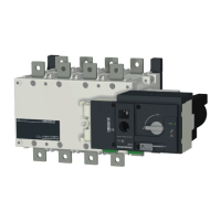
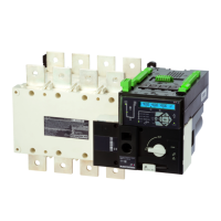
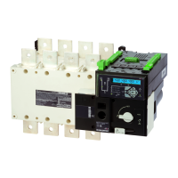
Motorised Changeover Switch
ATyS
1600A Ref : 95054160
Un
N°
PP / PN
1: 220 / 127
2: 380 / 220
3: 400 / 230
4: 415 / 240
5: 480 / 277
6: 208 / 120
7: 220 / 127
8: 230 / 132
9: 240 / 138
10: 380 / 220
11: 400 / 230
12: 415 / 240
13: 480 / 277
5
6
7
8
9
10
11
12
13
14
15
16
18
20
1:
2:
3:
4:
5:
6:
7:
8:
9:
10:
11:
12:
13:
14:
3
3
4
4
5
5
6
6
7
7
8
8
9
10
N°: Δ
U
Δ
F
%
XXX
50 Hz60 Hz
XXXXXXXX
Set Pot
PROG
AUT
Press
60ms
Press
2s
Ready !
PROG
Set Dip
1 2 3
45
PROG
POWER
AUT
Ø 4 ... 8mm
PROG
OK
AUT
READY
ATyS t
0
1
5
10
20
60
0
1
5
10
20
60
G: U
10% F
5%
H: U
20% F
10%
E:
F:
REMOTE CONTROL
A: 3 Ph
B: 1 Ph
C: Neutral
D: Neutral
Motorised Changeover Switch
ATyS
1600A Ref : 95054160
Un
N°
PP / PN
1: 220 / 127
2: 380 / 220
3: 400 / 230
4: 415 / 240
5: 480 / 277
6: 208 / 120
7: 220 / 127
8: 230 / 132
9: 240 / 138
10: 380 / 220
11: 400 / 230
12: 415 / 240
13: 480 / 277
5
6
7
8
9
10
11
12
13
14
15
16
18
20
1:
2:
3:
4:
5:
6:
7:
8:
9:
10:
11:
12:
13:
14:
3
3
4
4
5
5
6
6
7
7
8
8
9
10
N°: Δ
U
Δ
F
%
XXX
50 Hz60 Hz
XXXXXXXX
Set Pot
PROG
AUT
Press
60ms
Press
2s
Ready !
PROG
Set Dip
1 2 3
45
PROG
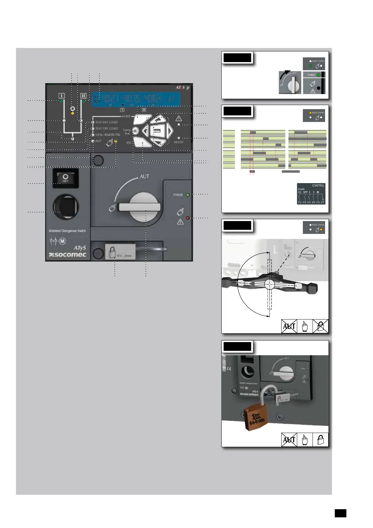
STEP 7D
Padlocking Mode
(as standard : in position O)
3x
Ø 4-8 mm
1. MANUAL Mode LED indication. (Yellow
steady light when in Manual Mode).
2. AUTO Mode LED indication Green steady
light when in Auto mode with no timers
running.
Green flashing light when in Auto with timers
running.
3. LOCAL / REMOTE CONTROL Mode LED
indication.
Yellow steady light when in Local / Remote
control mode.
Remote control mode is achieved with the
Auto/Manu selector switched to Auto and
terminals 312 closed with terminal 317.
Remote control orders are received through
closing 314 to 316 with 317.
REMOTE Control is also achievable through
EasyConfigATySpsoftwarewhen
connected to the product through Ethernet or
MODBUS. (Optional modules). Local Control
selectable and operable through the ATyS
p keypad.
4. TEST ON LOAD CONTROL Mode LED
indication. (Yellow steady light when in TON/
EONmode)
5. TEST OFF LOAD CONTROL Mode LED
indication. (Yellow steady light when in TOF/
EOF mode).
6. Load Supply On LED. (Green when the load
is supplied).
7. Switch 1 LED position indication. (Green
when in position 1).
8. Source supply I availability LED indication.
(Green when supply I voltage is within the
set limits).
9. Zero position LED indication. (Yellow when
in position 0).
10. Switch 2 LED position indication. (Green
when in position 2).
11. Source supply II availability LED indication.
(Green when supply II voltage is within the
set limits).
12. LCD Display Screen : (Status,
measurement, timers, counters, events,
faults, programming …. )
13. MODE key to shift between operation
modes.
14. Navigation Keys to browse through the
ATyS p menus without software.
15. FAULT LED indication. (Red steady light
in case of an ATS controller internal fault.
Switch the product from Auto to Manual
and back to Auto to reset a fault condition).
16. READY LED indication. (Green steady
light : Product is powered and in AUTO,
Watchdog OK, The Product is Available to
changeover).
17. Enter Key used to enter Prog Mode (Press
and hold for 5 seconds) and to validate the
settings programmed through the keypad.
18. ESC key used to escape from a specific
screen up to the main menu.
19. Lamp test key to check the LED’s and LCD
screen.
20. Green LED Indication: Power
21. Red LED Indication: Product Unavailable /
Manual Mode / Fault Condition
22. Auto / Manual mode selector switch
(Key version available as an option)
23. Padlocking facility
(Up to 3 padlocks of dia. 4 - 8mm)
24. Emergency manual operation shaft location
(Accessible only in manual mode)
25. Switch position indication window:
I (On switch I) O (Off) II (On switch II).
2223
24
25
8
7
2
3
4
5
1
6
15
20
21
17
18
13
14
19
1110 129
Pr ogramming the ATyS p
1
SETUP
2
VOLT. LEVELS
3
FREQ. LEVELS
4
PWR. LEVELS
5
TIMERS VALUE
6
I-O
7
COMM
8
DATE/TIME
NETWORK 4NBL OV. U i 115% O V. F i 105% OV.P i 0000 kVA 1FT 0003 SEC IN 1 --- NO DHCP NO (9) YEAR
AUTOCONF NO (7) OV. U HYS i 110% OV. F HYS i 103% OV.P HYS i 0000 kVA 1RT 0180 SEC IN 2 --- NO IP 1-2 192.168.
(9)
MONTH
NEUTRAL AUTO UND. U i 085% UND. F i 095% OV.P i i 0000 kVA 2FT 0003 SEC IN 3 --- NO IP 3-4 .002.001 DAY
ROT PH. --- UND. U HYS i 095% UND. F HYS i 097% OV.P HYS i i 0000 kVA 2RT 0005 SEC (2) IN 4 --- NO GAT1-2 000.000.
(9)
HOUR
NOM. VOLT 400 V UNB. U i 00% O V. F i i 105% 2AT 0005 SEC (1) IN 5 --- NO GAT3-4 .000.000 MINUTE
NOM. FREQ 50 Hz UNB. U HYS i 00% OV. F HYS i i 103% 2CT 0180 SEC (1) IN 6 --- NO MSK1-2 255.255.
(9)
SECOND
APP M-G OV. U i i 115% UND. F i i 095% 2ST 0030 SEC (1) IN 7 --- NO (8) MSK3-4 .255.000
PRIO TON NO (1) OV. U HYS i i 110% UND. F HYS i i 097% ODT 0003 SEC IN 8 --- NO (8) ADDRESS 005
PRIO EON NO (3) UND. U i i 085% TOT UNL (1) IN 9 --- NO (8) BDRATE 9600
PRIO NET 1 (2) UND. U HYS i i 095% TOT 0010 SEC (1) IN10 --- NO (8) STOP BIT 1
RETRANS NO UNB. U i i 00% T3T 0000 SEC (1) IN11 --- NO (8) PARITY NONE
CT PRI 100 UNB. U HYS i i 00% TFT UNL (1) IN12 --- NO (8)
CT SEC 5 TFT 0600 SEC (1) IN13 --- NO (8)
S1=SW2 NO E1T 0005 SEC (3) IN14 --- NO (8)
BACKLGHT INT E2T UNL (3) OUT 1 POP NO
CODE P 1000 E2T 0010 SEC (3) OUT 2 --- NO (8)
CODE E 0000 E3T 0005 SEC (3) OUT 3 --- NO (8)
BACKUP SAVE E5T 0005 SEC (4) OUT 4 --- NO (8)
E6T LIM (4) OUT 5 --- NO (8)
E6T 0600 SEC (4) OUT 6 --- NO (8)
E7T 0005 SEC (4) OUT 7 --- NO (8)
LST 0004 SEC (5) OUT 8 --- NO (8)
EET 0168 H (6) OUT 9 --- NO (8)
EDT 1800 SEC (6)
16
(1) When «APP» is set to «M-G»
(2) When «APP» is set to «M-M»
(3) When one of the I/P is set to «EON»
(4) When one of the I/P is set to «EOF»
(5) When one of the O/P is set to «LSC»
(6) When one of the O/P is set to «EES»
(7) If the product is in manual mode
(8) With optional I/O modules
(9) With Ethernet module
The ATyS p is to be programmed powered up and after wiring
verication tests. This may either be done through the front of
the ATS Controller using the keypad or with the user-friendly Easy
Congsoftware.
Forconvenience,werecommendtousetheEasyCongsoftware.
(Downloadable free from www.socomec.com).
The ATyS p is delivered with default setting values based on
most used customer application requirements. The minimum
conguration parameters that must be programmed arethe type
of network and application together with the voltage and frequency
nominalvalues.ATySpAutoCongurationmakesthesetupofVolts,
Hz, Phase rotation and Neutral Position quick and easy.
A - Programming with Easy Config Software
To program the ATyS p using Easy Cong software simply follow
the setting boxes from left to right until all desired settings in each
window have been completed. Help pop ups are included to show
the minimum and maximum setting values allowed. The software
includes most SOCOMEC products so before programming click
NEW and select the product “ATyS p” from the list of products
available.
When the ATyS p is powered and communicating, the software will
include a screen to monitor and display the ATyS p status.
Control through software (such as changing switch position I-O-II) is
also possible when in Super User Mode.
To change the conguration: Enter code (factory code = 1000) using navigation push buttons (14).
Programming exit: Press and hold for 5 s “Validation” push button (17).
Note 1: Values as listed above are the setting values by default.
Note 2: Ensure that the Default Network Setting and Application match the installation or change
accordingly before using Auto Conguration.
B - Programming with the ATyS p keypad
STEP 6
Check
Whilst in manual mode, check the
wiring and if ok power up the
product.
LED “Power” Green: ON
LED Manuel/Fault Red: ON
STEP 5
Dual auxiliary supply:
Uc 208-277V~ +/-20% 50/60Hz
Power comsumption: 22VA
See instruction sheet
ATS CONTROLLER
To D10
To D20
64B 63B
64B 63B
417 416 415 414 413
207 208 209 210
417 416 415 414 413
207 208 209 210
7172 74
7172 74
ATyS t
Dual auxiliary supply:
Uc 208-277V~ +/-20% 50/60Hz
Power comsumption: 22VA
See instruction sheet
ATS CONTROLLER
ATyS p
Dual auxiliary supply:
Uc 208-277V~ +/-20% 50/60Hz
Power comsumption: 22VA
See instruction sheet
ATS CONTROLLER
ATyS g
Dual auxiliary supply:
Uc 208-277V~ +/-20% 50/60Hz
Power comsumption: 22VA
See instruction sheet
ATS CONTROLLER
To D10
To D20
64B 63B
64B 63B
417 416 415 414 413
207 208 209 210
417 416 415 414 413
207 208 209 210
7172 74
7172 74
ATyS t
Dual auxiliary supply:
Uc 208-277V~ +/-20% 50/60Hz
Power comsumption: 22VA
See instruction sheet
ATS CONTROLLER
ATyS p
Dual auxiliary supply:
Uc 208-277V~ +/-20% 50/60Hz
Power comsumption: 22VA
See instruction sheet
ATS CONTROLLER
ATyS g
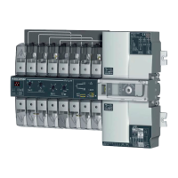
Optional Modules
Communication between the software and the ATyS p may be done through the Ethernet/Modbus TCP or Modbus RTU modules
that are available as an option. The ETHERNET / MODBUS modules are to be installed in one of the slots provided in the ATYS p
ATS control unit.
Easy Cong may be used with a PC connected or through
ETHERNET or MODBUS modules as well as isolated from
the product and simply saved on a PC for download at any
convenient time.
Note: The ATyS p may accept a total of 4 additional Input /
Output modules offering an additional 8 programmable inputs
and 8 programmable outputs. When including a MODBUS
module the ATySp accepts a total of 3 I/O modules and when
including the ETHERNET module a total of 2 I/O modules.
Refer to the ATyS p accessory section for details.
Setup by Auto Conguration
(Volts, Hz, Neutral pos., Ph rotation)
Press 5s
Go To
1
SETUP
Scroll to
AUTOCONF
Enter code 1000
Set to
YES
Press 60 ms
LEDsash
Save : press 5s
Note: Source
I
or source
II
must be
available to set by Auto Conguration.
ATyS p devices may also be programmed through the ATS controller keypad.
This programming method is necessary for products not equipped with Ethernet
or Modbus communication modules that facilitate programming through
Easy Cong software described above.The keypad is a useful interface and
programming method most especially when changing a few parameters or
simply interrogating the product.
Programming access: Press and hold for 5 s “Validation” push button (17).
Access through the keypad is possible in Automatic or Manual mode, when the
product is in a stable position (I, 0 or II) with at least one supply source available.
Programming is not accessible whilst any cycle sequence is running.
3 phase / 4 wire 3 phase / 3 wire 2 phase / 3 wire 2 phase / 2 wire 1 phase / 2 wire
4NBL
4BL
1
N
17
14
The Ethernet module includes a built in Web Server for
Monitoring, Engine Exerciser Control, Events...
Extended I/O
2xIP 2xO/P
Modbus
RS485
Pulsed O/P 4-20mA
Ethernet/Modbus
TCP Simple
orGateway
 Loading...