1x 1x
confirm
1x (1BL)
2x (2BL)
3x (3BL)
4x (3NBL)
5x (4BL)
6x (4NBL)
1x
3 sec
1x 1x 1x
confirm
1x 1x
confirm
1x (20 min)
2x (30 min)
3x (60 min)
4x (2 sec)
5x (5 min)
6x (8 min)
7x (10 min)
8x (15 min)
1x 1x
confirm
1x (20 min)
2x (30 min)
3x (60 min)
4x (2 sec)
5x (5 min)
6x (8 min)
7x (10 min)
8x (15 min)
1x 1x 1x 7x 1x
confirm
1x 1x 1x 1x 1x 1x 1x 1x 1x 1x 1x 1x 1x 1x 1x 1x 1x 1x 1x
FONCTION DE TEST DU RACCORDEMENT
Connection test function - Anschluss functionstest - Collegamento prova funzione - Aansluiting test functie - Conexion prueba funcion - Ligaçao teste função
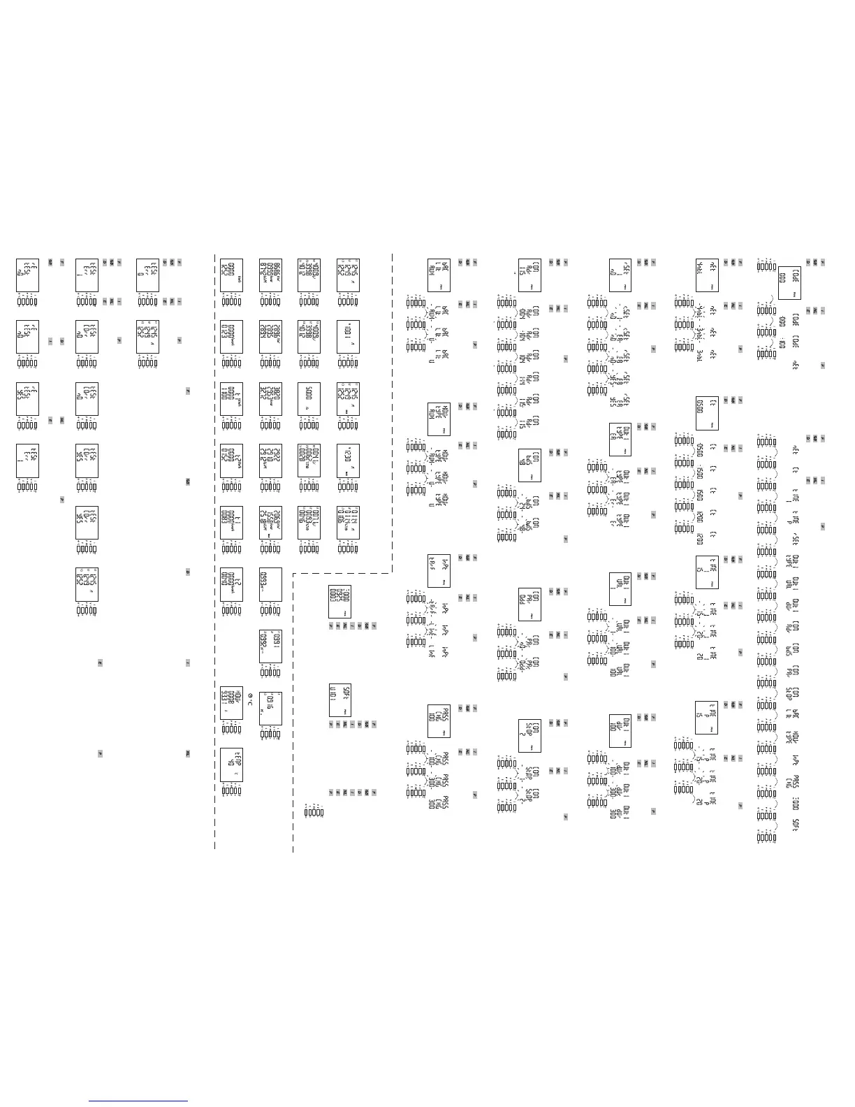
PROGRAMMATION
Programming - Konfiguration - Programmazione - Programmering - Programacion - Programação
1x
3 sec.
1x 1x 1x
Lors du test, le DIRIS doit avoir du courant et de la tension
sur chacune des phases. De plus, cette fonction considère
que le FP de l’installation est compris entre 0,6 < FP < 1.
Si le FP de l’installation n’est pas compris dans cette zone,
cette fonction ne peut être utilisée.
En 4 BL / 3 BL / 2BL / 1 BL,
le raccordement des TI est uniquement contrôlé.
En 4NBL et 3 NBL l’ensemble du raccordement est contrôlé.
Err 0 = aucune erreur
Err 1 = inversion du raccordement du TC sur la phase 1
Err 2 = inversion du raccordement du TC sur la phase 2
Err 3 = inversion du raccordement du TC sur la phase 3
Err 4 = inversion en tension entre V1 et V2
Err 5 = inversion en tension entre V2 et V3
Err 6 = inversion en tension entre V3 et V1
Pour les Err 1, Err 2 et Err 3, la modification peut se faire via
le DIRIS ou manuellement en corrigeant le raccordement
des courants.
Pour les Err 4, Err5 et Err 6 la modification doit se faire
manuellement en corrigeant le raccordement des tensions.
During the test, the DIRIS must have current and voltage for
each of the phases. In addition to this, the function recognises
the PF of the installation as being between 0.6 < PF < 1.
If the PF of the installation is not within this range, this function
cannot be used.
In 4 BL/3 BL/2BL/1 BL,
the connection of the CTs is controlled only.
In 4NBL and 3NBL the connection as a whole is controlled.
Err 0 = no error
Err 1 = CT phase 1 inverted
Err 2 = CT phase 2 inverted
Err 3 = CT phase 3 inverted
Err 4 = V1 and V2 voltages inverted
Err 5 = V2 and V3 voltages inverted
Err 6 = V3 and V1 voltages inverted
For the Err 1, Err 2 and Err 3, the modification can be
performed by the DIRIS or manually by correcting
the current connections.
For the Err 4, Err 5 and Err 6 the modification must be
performed manually by correcting the voltage connections.
Menu programmation
Programming menu
Konfiguration Menü
Programmazione rapporto
Programacion menù
Programmatie menu
Programação menu
Réseau
Exemple : NET = 3NBL
Network
Example : NET = 3NBL
Netzfrequenz
Beispiel : NET = 3NBL
Freqenza
Esempio : NET = 3NBL
Frecuencia
Ejemplo : NET = 3NBL
Netfrequentie
Voorbeeld : NET = 3NBL
Frequência
Exemplo : NET = 3NBL
1x
3 sec.
1x 3 sec.
pour sortir du programme
Exemple : tESt Err 0
Example : tESt Err 0
Beispiel : tESt Err 0
Esempio : tESt Err 0
Ejemplo : tESt Err 0
Voorbeeld : tESt Err 0
Exemplo : tESt Err 0
1x
3 sec.
1x 1x 1x 1x 1x 3 sec.
pour sortir du programme
Exemple : tESt Err 1
Example : tESt Err 1
Beispiel : tESt Err 1
Esempio : tESt Err 1
Ejemplo : tESt Err 1
Voorbeeld : tESt Err 1
Exemplo : tESt Err 1
> 2ème opération de test
Remarque : cette opération ne tient pas compte
des modifications éffectuées lors du premier test.
> second test operation
NB : this operation does not hold account of the
modifications carried out at the time of the first test.
> Zweiter Testbetrieb
Hinweis : Bei diesem Betrieb werden die Änderungen
aus dem ersten Test nicht berücksichtigt.
> 2a operazione di test
Nota : questa operazione non tiene conto delle
modifiche compiute in occasione del primo test.
> segunda operacion de prueba
Nota : operacion ne tiene en cuenta las modificaciones
efectuadas en la primer prueba.
> 2e testoperatie
Opmerking : deze poeratie houdt geen rekening met
de wijzigingen aangebracht tijdens de eerste test.
> 2a operação de teste
Nota : esta operação não leva em conta as modificações
efectuadas durante o primeiro teste.
1x 1x1x P (max P)
2x EA (kWh)
3x Er (kvarh)
4x I (max 4I)
1x 1x
confirm
1x 1x
confirm
1x Er (kvarh)
2x ALAr
3x Cd
4x EA (kWh)
Remise à zéro
Exemple : rSET = Ea
Reset to zero
Example : rSET = Ea
Rückstellungen
Beispiel : rSET = Ea
Azzeramento
Esempio : rSET = Ea
Volver a cero
Ejemplo : rSET = Ea
Reset
Voorbeeld : rSET = Ea
Colocações a zero
Exemplo : rSET = Ea
Type de sortie
Exemple : OUt I tyPE = Er
Pulse output type
Example : OUt I tyPE = Er
Typs des Ausgangs
Beispiel : OUt I tyPE = Er
L'uscita ad impulsi
Esempio : OUt I tyPE = Er
Tipo de salida de impulsos
Ejemplo : OUt I tyPE = Er
Type pulsuitegang
Voorbeeld : OUt I tyPE = Er
Tipo de saída
Exemplo : OUt I tyPE = Er
1x 1x
confirm
1x (10)
2x (100)
3x (1 M)
4x (10 M)
5x (0.1)
6x (1)
Poids de la sortie
Exemple : OUt I VAL = 100
Pulse output rate
Example : OUt I VAL = 100
Ausgangsimpulswertigkeit
Beispiel : OUt I VAL = 100
Peso degli uscita impulsi
Esempio : OUt I VAL = 100
Peso de la salida de impulsiones
Ejemplo : OUt I VAL = 100
Gewicht van pulsuitegang
Voorbeeld : OUt I VAL = 100
Peso da saída de impulsães
Exemplo : OUt I VAL = 100
1x 1x
confirm
1x (200)
2x (300)
3x (400)
4x (500)
5x (600)
6x (700)
7x (800)
8x (900)
9x (100)
Durée du pulse
Exemple : OUt I dUr = 300
Pulse output durations
Example : OUt I dUr = 300
Dauer des Impulsausgangs
Beispiel : OUt I dUr = 300
Durata dell' uscita ad impulsi
Esempio : OUt I dUr = 300
Duración de la salida impulsiones
Ejemplo : OUt I dUr = 300
Duur van de pulsenuitgang
Voorbeeld : OUt I dUr = 300
Duração da saida de
impulsões
Exemplo : OUt I dUr = 300
Intégration des courants
Exemple : tIME = 20 min
Integration time
Example : tIME = 20 min
Integrationszeit des shöme
Beispiel : tIME = 20 min
Intégrazione delle corenti
Esempio : tIME = 20 min
Integracion de las intensidades
Ejemplo : tIME = 20 min
Integratietijd van de stromen
Voorbeeld : tIME = 20 min
Integração das cotentes
Exemplo : tIME = 20 min
Transformateur de courant
Exemple : Ct = 1200 / 5
Current transformers
Example : Ct = 1200 / 5
Phasenstromwandlers
Beispiel : Ct = 1200 / 5
Transformatore di corrente
Esempio : Ct = 1200 / 5
Transformador de corrente
Ejemplo : Ct = 1200 / 5
Stroomtransformator
Voorbeeld : Ct = 1200 / 5
Transformador de corrente
Exemplo : Ct = 1200 / 5
Intégration de la puissance active
Exemple : tIME = 20 min
Integration active time
Example : tIME = 20 min
Integrationszeit des Wirkleistung
Beispiel : tIME = 20 min
Integrazione potenza attiva
Esempio : tIME = 20 min
Integracion de las potencia activa
Ejemplo : tIME = 20 min
Integratietijd van de actief vermogen
Voorbeeld : tIME = 20 min
Integração das potência activa
Exemplo : tIME = 20 min
Prog 3 sec.
Quitter la programmation
To quit programming
Konfigurationsebene verlassen
Per abbandonare la programmazione
Para salirde la programacion
Om vit programmering te gaan
Para sair da programação
1x 1x
confirm
1x (I)
2x (U)
3x (AUX)
Rétroéclairage
Exemple : bACLIt = U
Backlit
Example : bACLIt = U
LCD Anzeige von hinten
beleuchtet
Beispiel : bACLIt = U
Retroiluminato
Esempio : bACLIt = U
Retroiluminacion
Ejemplo : bACLIt = U
Backlight
Voorbeeld : bACLIt = U
Retroiluminação
Exemplo : bACLIt = U
1x 1x
confirm
1x (I)
2x (U)
3x (INPt)
4x (AUX )
Compteur horaire
Exemple : HOUr = U
Hour run meter
Example : HOUr = U
Stundenzähler
Beispiel : HOUr = U
Contatore orario
Esempio : HOUr = U
Contador horario
Ejemplo : HOUr = U
U renteller
Voorbeeld : HOUr = U
Contador horário
Exemplo : HOUr = U
1x 1x
confirm
1x (LInE)
2x (tArF)
Entrée
Exemple : InPt = LInE
Input
Example : InPt = LInE
Eingang
Beispiel : InPt = LInE
Entrate
Esempio : InPt = LInE
Entrada
Ejemplo : InPt = LInE
Ingage
Voorbeeld : InPt = LInE
Entrada
Exemplo : InPt = LInE
1x 1x
confirm
1x (200)
2x (300)
3x (400)
4x (500)
5x (600)
6x (700)
7x (800)
8x (900)
9x (000)
10x (100)
Changement de code
Exemple : PASS = 300
Code Change
Example : PASS = 300
Codeänderung
Beispiel : PASS = 300
Cambiamento di codice
Esempio : PASS = 300
Cambio de còdigo
Ejemplo : PASS = 300
Verandering van code
Voorbeeld : PASS = 300
Mudança de còdigo
Exemplo : PASS = 300
Version logiciel
Software version
Softwareversion
Versione software
Version de software
Softwareversie
Versão do software
Numéro de série
Exemple : 0000925003
Serial number
Example : 0000925003
Seriennummer
Beispiel : 0000925003
Numero di serie
Esempio : 0000925003
Numero de serie
Ejemplo : 0000925003
Seriennummer
Voorbeeld : 0000925003
Numero de serie
Exemplo : 0000925003
Entrée en programmation
Code = 100
Acces to programming mode
Code = 100
Zur Konfigurationsebene
Code = 100
Accesso alla programmazione
Code = 100
Entar em modo programacion
Code = 100
Overgaan tot programmeermodus
Code = 100
Entar em modo programação
Code = 100
Beim Test muss DIRIS an jeder der Phasen Strom und Spannung
haben. Des Weiteren geht diese Funktion davon aus, dass der
Leistungsfaktor der Installation zwischen 0,6 < LF < 1 liegt.
Wenn der LF der Installation nicht innerhalb dieses Bereichs liegt,
kann diese Funktion nicht verwendet werden.
Bei 4 BL / 3 BL / 2BL / 1 BL
wird nur der Anschluss der TI kontrolliert.
Bei 4NBL und 3 NBL wird der gesamte Anschluss kontrolliert.
Err 0 = kein Fehler
Err 1 = umwandlung des Stromwandlers auf Phase 1
Err 2 = umwandlung des Stromwandlers auf Phase 2
Err 3 = umwandlung des Stromwandlers auf Phase 3
Err 4 = umwandlung der Spannung zwischen V1 und V2
Err 5 = umwandlung der Spannung zwischen V2 und V3
Err 6 = umwandlung der Spannung zwischen V3 und V1
Für die Err 1, Err 2 und Err 3 kann die Änderung über
das DIRIS oder manuell durch Korrektur
der Stromanschlüsse erfolgen.
Für die Err 4, Err 5 und Err 6 muss die Änderung manuell
durch Korrektur des Anschlusses der Spannungen erfolgen.
Al momento del test, il DIRIS deve avere corrente e tensione
su ciascuna fase. Inoltre, questa funzione considera l’FP
dell’installazione compreso tra 0,6 < FP < 1.
Se l’FP dell’installazione non è compreso in questo intervallo,
la funzione non può essere utilizzata.
Il collegamento dei TI è controllato unicamente in
4 BL/3 BL/2BL/1 BL.
L’insieme del collegamento è controllato in 4NBL e 3 NBL.
Err 0 = nessun errore
Err 1 = inversione del raccordo del TC sulla fase 1
Err 2 = inversione del raccordo del TC sulla fase 2
Err 3 = inversione del raccordo del TC sulla fase 3
Err 4 = inversione in tensione tra V1 e V2
Err 5 = inversione in tensione tra V2 e V3
Err 6 = inversione in tensione tra V3 e V1
Per quanto riguarda gli Err 1, Err 2 e Err 3, la modifica si può
applicare tramite DIRIS o manualmente,
correggendo il collegamento delle correnti.
Per quanto riguarda gli Err 4, Err5 e Err 6, la modifica si deve
applicare manualmente, correggendo il collegamento delle tensioni.
Tijdens de test moet de DIRIS stroom hebben en spanning op
beide fasen. Bovendien is deze functie gebaseerd op een FP van
de installatie tussen 0,6 < FP < 1.
Als de FP van de installatie zich niet binnen deze zone bevindt kan
deze functie niet worden gebruikt.
In 4 BL / 3 BL / 2BL / 1 BL, wordt alleen de aansluiting van de
TI’s gecontroleerd.
In 4NBL en 3 NBL wordt het geheel van de aansluiting gecontroleerd.
Err 0 = geen enkele fout
Err 1 = inversie van de aansluiting van de spanningstransformator op fase 1
Err 2 = inversie van de aansluiting van de spanningstransformator op fase 2
Err 3 = inversie van de aansluiting van de spanningstransformator op fase 3
Err 4 = Spanningsinversie tussen V1 en V2
Err 5 = Spanningsinversie tussen V2 en V3
Err 6 = Spanningsinversie tussen V3 en V1
Voor Err 1, Err 2 en Err 3, kan de wijziging plaatsvinden via de DIRIS of
handmatig door de aansluiting van de stromen te corrigeren.
Voor de Err 4, Err5 en Err 6 moet de wijziging handmatig worden doorgevoerd
door middel van het corrigeren van de aansluiting van de spanningen.
Durante la prueba, el DIRIS debe recibir corriente y tensión en
cada una de las fases.
Además, esta función considera que el factor de potencia (FP)
de la instalación se encuentra entre 0,6> FP < 1.
Si el FP de la instalación no está en ese intervalo,
no se podrá utilizar la función.
En los modelos 4 BL / 3 BL / 2BL / 1 BL, únicamente está
controlada la conexión de los TI.
En los modelos 4 NBL y 3 NBL están controladas todas
las conexiones.
Err 0 = ningún error
Err 1 = inversión de la conexíon TC fase 1
Err 2 = inversión de la conexíon TC fase 2
Err 3 = inversión de la conexíon TC fase 3
Err 4 = inversión intensión entre V1 e V2
Err 5 = inversión intensión entre V2 e V3
Err 6 = inversión intensión entre V3 e V1
En el caso de los modelos Err 1, Err 2 y Err 3, la modificación
puede realizarse de forma automática a través del DIRIS o
manual por medio de la corrección de la conexión de la corriente.
En el caso de los modelos Err 4, Err5 y Err 6, la modificación
puede realizarse de forma manual por medio de la corrección
de la conexión de la tensión.
Durante o teste, o DIRIS deve ter corrente e tensão em cada
uma das fases.
Além disso, esta função considera que o FP da instalação
está compreendido entre 0,6 > FP < 1.
Se o FP da instalação não estiver dentro deste intervalo, esta
função não poderá ser utilizada.
Em 4 BL / 3 BL / 2BL / 1 BL, a ligação dos TI só é controlada.
Em 4NBL e 3 NBL, é controlado o conjunto da ligação.
Err 0 = nenhum erro
Err 1 = inversão da ligação do TC na fase 1
Err 2 = inversão da ligação do TC na fase 2
Err 3 = inversão da ligação do TC na fase 3
Err 4 = inversão em tensão entre V1 e V2
Err 5 = inversão em tensão entre V2 e V3
Err 6 = inversão em tensão entre V3 e V1
Para os Err 1, Err 2 e Err 3, a modificação pode ser
feita automaticamente, através do DIRIS, ou manualmente,
corrigindo a ligação das correntes.
Para os Err 4, Err5 e Err 6, a modificação pode ser
feita manualmente, corrigindo a ligação das tensões.
I
x1 x2 x3 x4 x5
U/F
x1 x2 x3 x4 x5
P/PF
x1 x2 x4 x5x3 x6 x7 x8
E
x1 x2 x3 x4 x5 x6
UTILISATION
Operation - Betrieb - Utilizzo - Gebruik - Utilizacion - Utilização
x1 x2
1x 1x
confirm
1x (2,4)
2x (4,8)
3x (9,6)
4x (19,2)
5x (38,4)
Vitesse de communication
Exemple : bdS = 4,8
Communication speed
Example : bdS = 4,8
Velocita di comunicazione
Esempio : bdS = 4,8
Velocidad de comunicaciòn
Ejemplo : bdS = 4,8
Communicatiesnelheid
Voorbeeld : bdS = 4,8
Velocidade de comunicação
Exemplo : bdS = 4,8
Kommunikationsges-
chwindigkeit
Beispiel : bdS = 4,8
1x 1x
confirm
1x (Odd)
2x (Even)
3x (nO)
Parité de communication
Exemple : PAr = Odd
Communication parity
Example : PAr = Odd
Parität
Beispiel : PAr = Odd
Bit di parita
Esempio : PAr = Odd
Paridad de comunicaciòn
Ejemplo : PAr = Odd
Communicatiepariteit
Voorbeeld : PAr = Odd
Paridade de comunicação
Exemplo : PAr = Odd
1x 1x
confirm
1x (1)
2x (2)
Bit de stop de communication
Exemple : PAr = Odd
Communication Stop bit
Example : PAr = Odd
Stop Bits
Beispiel : PAr = Odd
Bit di stop di comunicazione
Esempio : PAr = Odd
Bit de stop de comunicaciòn
Ejemplo : PAr = Odd
Communicatie-stopbit
Voorbeeld : PAr = Odd
Bit de stop de
comunicação
Exemplo : PAr = Odd
1x 1x
confirm
1x 1x0>2 0>9 1>9
Adresse de communication
Exemple : Adr = 115
Communication address
Example : Adr = 115
Kommunikations adresse
Beispiel : Adr = 115
Dell' indirizzo di comunicazione
Esempio : Adr = 115
Direccion de comunicaciòn
Ejemplo : Adr = 115
Het communicatieaders
Voorbeeld : Adr = 115
Endereço da comunicação
Exemplo : Adr = 115
Adr = 1 255
HEAD OFFICE SOCOMEC GROUP S. A. SOCOMEC capital 11 302 300 € R.C.S. Strasbourg B 548 500 149 B.P. 1,rue de Westhouse F-67235 Benfeld Cedex - FRANCEINTERNATIONAL SALES DEPARTMENT SOCOMEC 1, rue de Westhouse -B.P. 60010 F-67235 Benfeld Cedex - FRANCE Tel. +33 (0)3 88 57 41 41 - Fax +33 (0)3 88 74 08 00
 Loading...