1-24
MVS-8000 System
SYSTEM SETUP
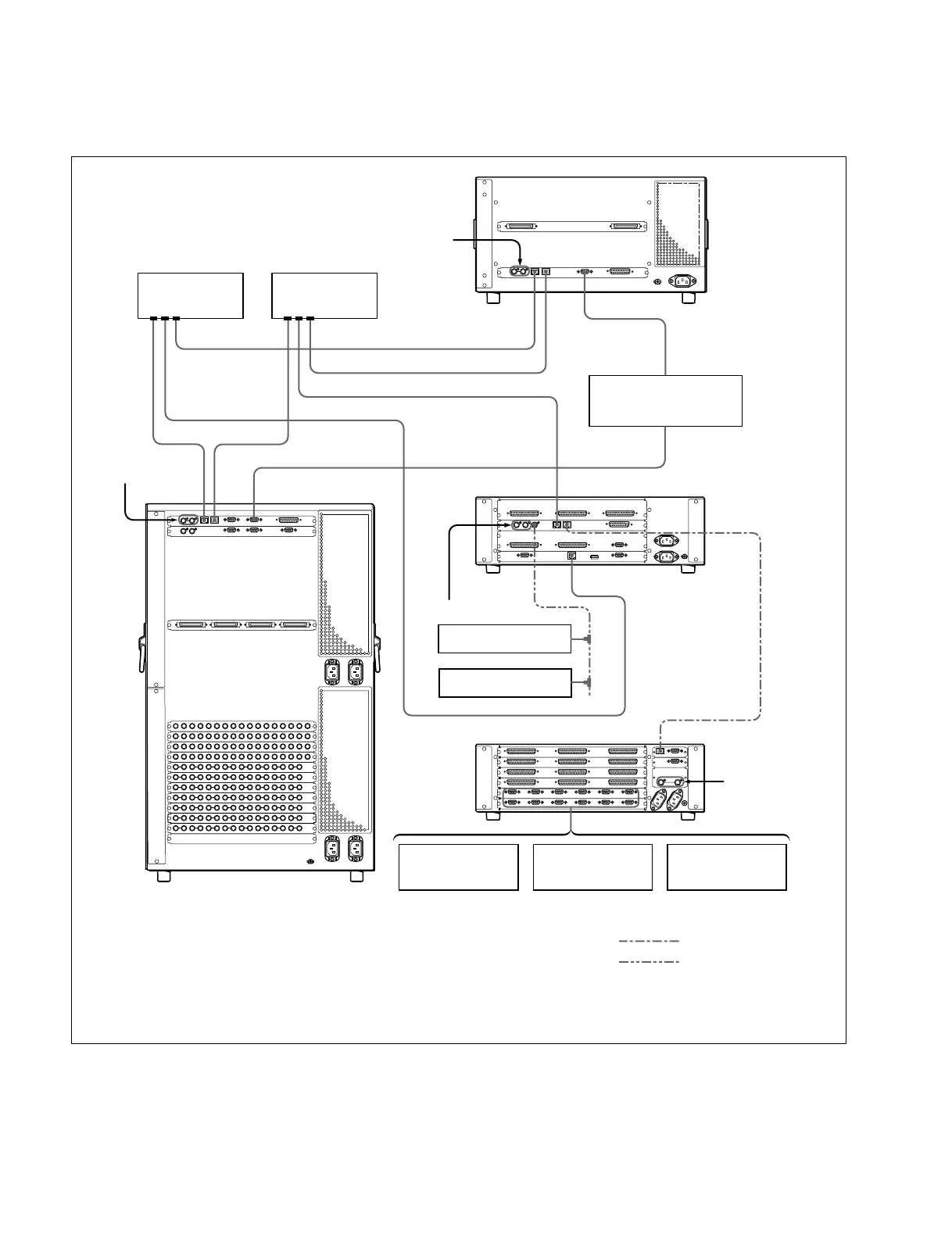
1-4. MVS-8000 System Example
1-4. MVS-8000 System Example
(*1) : Connect each LAN (CTRL, DATA) to the separate Ethernet switches respectively.
However, a single Ethernet switch can be used for connecting each LAN.
For information about Ethernet switches that can be used in an MVS system, contact your local Sony Sales Office/Service Center.
For detailed information about setting up the Ethernet switch, refer to the documentation supplied with the switch.
(*2) : Terminate the system with the 75 Z terminator supplied. The 75 Z terminator is supplied with the equipment.
Reference video
signal (*2)
CTRL
CTRL
EDITOR
DATA LAN
REMOTE
DATA CTRL REMOTE 1
DATA
PERIPH
PERIPH
Ethernet switch
(*1)
Ethernet switch
(*1)
Reference video signal (*2)
Reference video
signal (*2)
Reference video
signal (*2)
DME Processor Pack
MVE-8000
Editing Control System
BVE-9100
System Control Unit
MKS-8010
BKS-R series
HDS-X series
Device Control Unit Pack DCU-8000
VTR DDR
Audio mixer
Switcher Processor Pack
MVS-8400/8300/8200
Crossover cable
BNC cable
 Loading...