SERVICE MANUAL
LEVEL 2
Link
SERVICE NOTE
DISASSEMBLY
BLOCK DIAGRAMS
FRAME SCHEMATIC DIAGRAMS
SCHEMATIC DIAGRAMS
PRINTED WIRING BOARDS
REPAIR PARTS LIST
SPECIFICATIONS
SERVICE NOTE
DISASSEMBLY
BLOCK DIAGRAMS
FRAME SCHEMATIC DIAGRAMS
SCHEMATIC DIAGRAMS
PRINTED WIRING BOARDS
REPAIR PARTS LIST
SPECIFICATIONS
Link
Revision History
Revision History
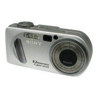
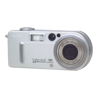
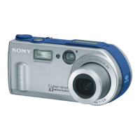
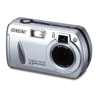
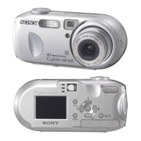
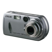
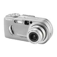
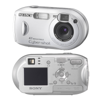
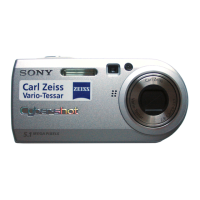
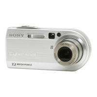
DSC-P8
•For ADJUSTMENTS (SECTION 6), refer to SERVICE MANUAL, ADJ (987622651.pdf).
•For INSTRUCTION MANUAL, refer to SERVICE MANUAL, LEVEL 1 (987622641.pdf).
• This service manual contains information for Japanese model as well.
• Reference No. search on printed wiring boards is available.
• Note in Lens Frame Installation
• BARRIER OPERATION TEST METHOD
• HELP: Sheet attachment positions and procedures of processing the flexible boards/harnesses are shown.
US Model
Canadian Model
AEP Model
UK Model
E Model
Hong Kong Model
Australian Model
Chinese Model
Korea Model
Tourist Model
Japanese Model
Ver 1.0 2003. 03
DIGITAL STILL CAMERA
On the JK-243, JK-244 and SY-83 boards
This service manual procides the information that is premised
the circuit board replacement service and not intended repair
inside the JK-243, JK-244 and SY-83 boards.
Therefore, schematic diagram, printed wiring board and
electrical parts list of the JK-243, JK-244 and SY-83 boards are
not shown.
The following pages are not shown.
JK-243, JK-244 boards
Schematic diagram ......................... Pages 4-35 to 4-36
Printed wiring board ........................ Pages 4-51 to 4-52
Electrical parts list ........................... Pages 5-6
SY-83 board
Schematic diagram ......................... Pages 4-9 to 4-28
Printed wiring board ........................ Pages 4-43 to 4-46
Electrical parts list ........................... Pages 5-9 to 5-13
The above-described information is shown in service
manual Level 3.