DIGITAL VIDEO CAMERA RECORDER
The information that is not described in this
Service Manual is described in the LEVEL 2
Service Manual.
When repairing, use this manual together with
LEVEL 2 Service Manual.
Contents of LEVEL 2 Service Manual
SERVICE NOTE
1. GENERAL
2. DISASSEMBLY
3. BLOCK DIAGRAMS
4. PRINTED WIRING BOARDS AND
SCHEMATIC DIAGRAMS
5. ADJUSTMENTS
6. REPAIR PARTS LIST
OVERALL
POWER
CD-349 BOARD
FP-386 BOARD
FP-383 BOARD
CONTROL SWITCH BLOCK
(ME-1850), (PS-1850), (FK-1850)
FP-100, FP-228, FP-102 FLEXIBLE BOARD
VM-027 BOARD
FLASH UNIT (MC-1850), (ST-1850)
KY-060 BOARD
FJ-035 BOARD
FP-387 BOARD
PD-148 BOARD
EXPLODED VIEWS
ELECTRICAL PARTS LIST
SERVICE MANUALSERVICE MANUAL
Level 3
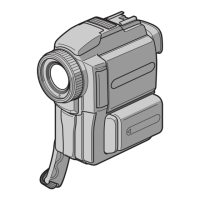
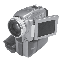
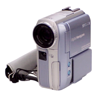
DCR-PC115/PC115E/
PC120BT/PC120E
RMT-811
Photo : DCR-PC120E
RMT-811
J MECHANISM
Canadian Model
DCR-PC120BT
AEP Model
DCR-PC115E/PC120E
UK Model
Australian Model
DCR-PC120E
E Model
DCR-PC115/PC115E/PC120E
Hong Kong Model
DCR-PC115/PC120E
Tourist Model
DCR-PC115/PC115E
Chinese Model
DCR-PC115E
Korea Model
DCR-PC115
Ver 1.3 2005. 06