DSC-F717
6-45
3. Bright Adjustment (PD-179 Board)
Set the D Range of the RGB decoder for driving the LCD to the
specified value.
If deviated, the EVF screen image will be blackish or saturated
(whitish).
Mode PLAY
Signal Arbitrary
Measurement Point Pin wa of CN305 on FR-194
board (EVF_VG)
Measuring Instrument Oscilloscope
Adjustment Page A
Adjustment Address 95
Specified Value A = 7.00 ± 0.10 Vp-p
Adjusting method:
Order Page Address Data Procedure
1 0 01 01
2 A 02 23 Press PAUSE button.
34 F103
4A 95
Change the data and set the
voltage (A) to the specified
value.
5 A 95 Press PAUSE button.
Processing after Completing Adjustments:
Order Page Address Data Procedure
1 A 02 00 Press PAUSE button.
24 F100
3 0 01 00
4. Contrast Adjustment (PD-179 Board)
Set the level of the VIDEO signal for driving the LCD to the speci-
fied value.
If deviated, the EVF screen image will be blackish or saturated
(whitish).
Mode PLAY
Signal Arbitrary
Measurement Point Pin wa of CN305 on FR-194
board (EVF_VG)
Measuring Instrument Oscilloscope
Adjustment Page A
Adjustment Address 9A
Specified Value A = 1.75 ± 0.10 Vp-p
Adjusting method:
Order Page Address Data Procedure
1 0 01 01
2 A 02 23 Press PAUSE button.
34 F103
4A 9A
Change the data and set the
voltage (A) to the specified
value.
5 A 9A Press PAUSE button.
Processing after Completing Adjustments:
Order Page Address Data Procedure
1 A 02 00 Press PAUSE button.
24 F100
3 0 01 00
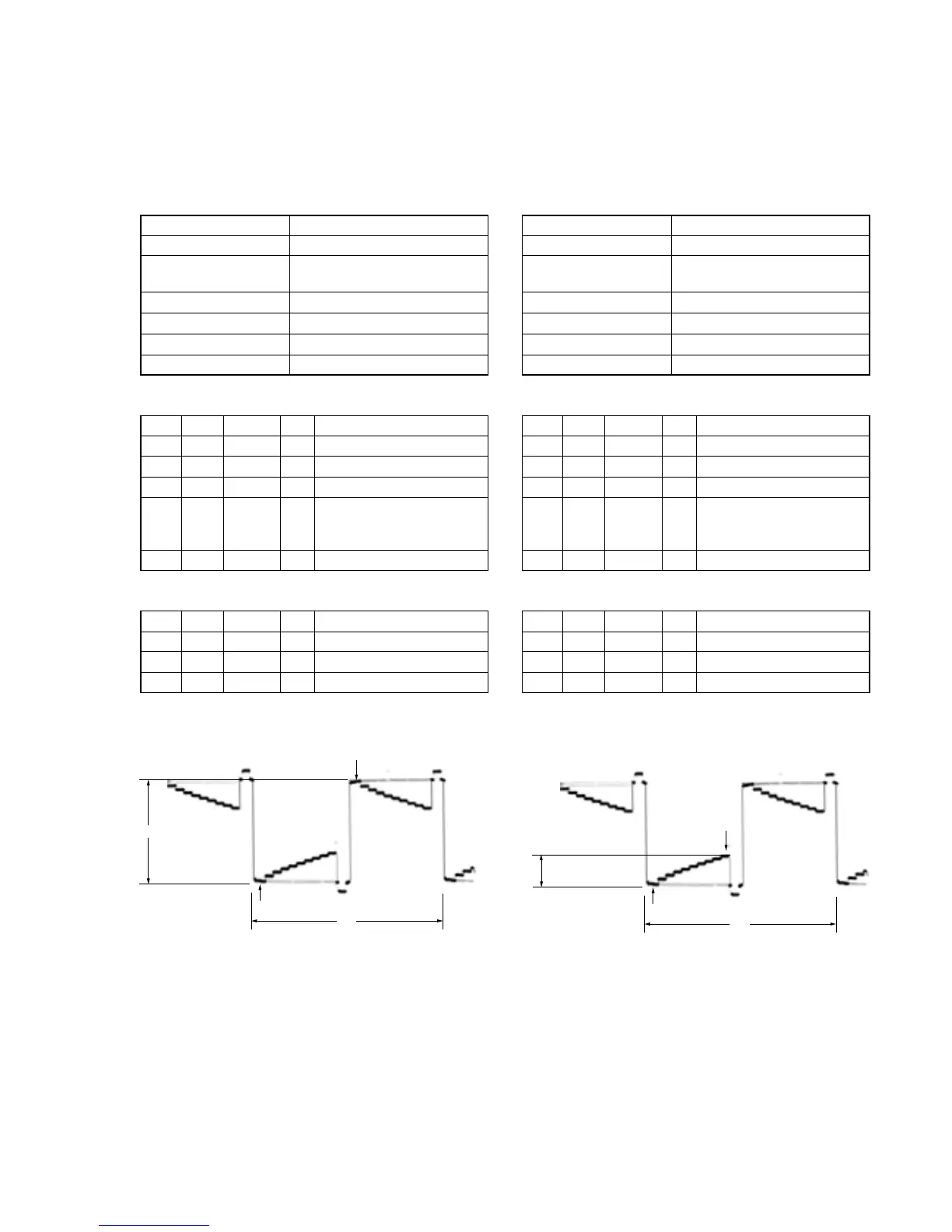
Fig. 6-1-24
2H
A
Pedestal
Pedestal
A: Between the reversed waveform pedestal and non-reversed
waveform pedestal
Fig. 6-1-25
2H
A
Pedestal
10 steps peak
A: Between the pedestal and 10 steps peak

 Loading...