HCD-SBT100/SBT100B/SBT300W/SBT300WB
5
CAPACITOR ELECTRICAL DISCHARGE PROCESSING
When checking the board, the electrical discharge is necessary for
the electric shock prevention.
Connect the resistor to both ends of respective capacitors.
• POWER board
C967
– POWER Board (Conductor Side) –
C967
800 Ω/2 W
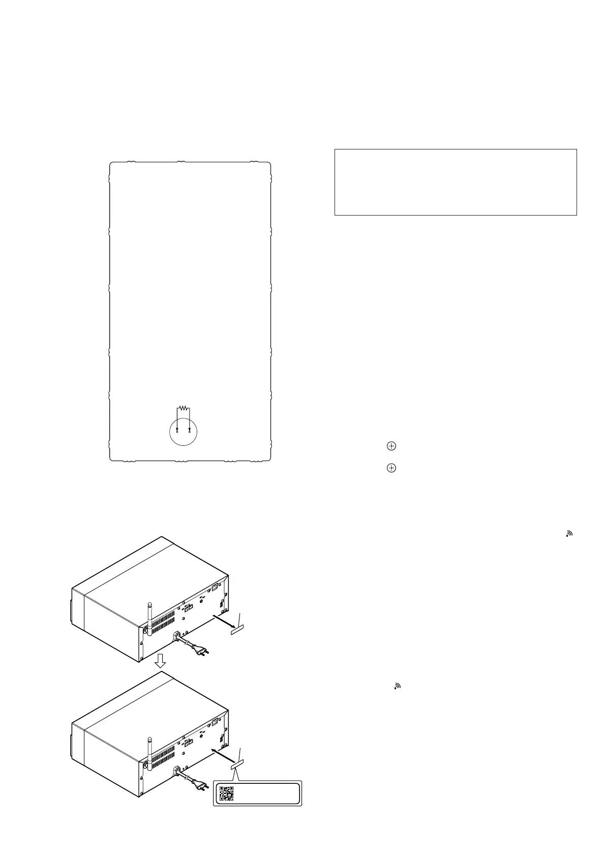
PROCESSING OF REPLACING THE WiFi MODULE
(Ref. No. WIFI1) (HCD-SBT300W/SBT300WB only)
When replacing the WiFi module (Ref. No. WIFI1), peel the de-
vice ID label stuck on the rear side of a main unit, and stick on the
new device ID label (refer to the following fi gure) enclosed with
the new WiFi module (Ref. No. WIFI1)
Device ID: XXXXXXXXXXXXX
MAC Address: XX-XX-XX-XX-XX-XX
1 Peel the device
ID label.
2 Stick on the new
device ID label.
– Rear view –
NOTE OF REPLACING THE WiFi MODULE (Ref. No.
WIFI1) (HCD-SBT300W/SBT300WB only)
When replacing the WiFi module (Ref. No. WIFI1), MAC address
is changed. Print the following explanation, cut it, and hand over
it to the customer with the unit, when returning the unit that the
repair is completed to the customer.
MAC address of this unit has been changed by this repair. The
customer who uses the MAC address fi ltering function of con-
nected access point equipment please set it again. MAC address
is possible to confi rm it on the Sony Network Device Setting
screen. Please refer to “Network connections” on the operating
instructions for details.
CHECKING METHOD OF NETWORK CONNECTION
(HCD-SBT300W/SBT300WB only)
It is necessary to check the network connection, when replacing
the complete MAIN board, complete NET board, IC101 on the
MAIN board or WiFi module (Ref. No. WIFI1). Check the con-
nection of wireless and wired LAN, according to the following
method.
1. Checking Method of Wireless LAN Connection
Necessary Equipment:
• Access point supporting WPS
Procedure:
1. Press the [
?/1
] button to turn the power on.
2. Press the [OPTIONS] button on the remote commander to the
display the setting menu on the fl uorescent indicator tube.
3. Press the [V]/[v] buttons on the remote commander to select
“WPS”.
4. Press the [ ] button on the remote commander.
(“OK” fl ashes on the fl uorescent indicator tube)
5. Press the [ ] button on the remote commander.
(“WPS” fl ashes on the fl uorescent indicator tube)
6. Press the [WPS] button on the access point.
7. When wireless LAN connection is started, “CONNECT”
fl ashes on the fl uorescent indicator tube.
8. When wireless LAN connection is completed, “COMPLETE”
appears for a moment on the fl uorescent indicator tube, then “
”
appears on the fl uorescent indicator tube.
9. Press the [
?/1
] button to turn the power off.
Note: Refer to the instruction manual about details of the setting method.
2. Checking method of wired LAN connection
Necessary Equipment:
• Router
• Network (LAN) cable
Procedure:
1. Connect the main unit to the router with the LAN cable.
2. Press the [
?/1
] button to turn the power on.
3. Check that “ ” appears on the fl uorescent indicator tube.
4. Press the [
?/1
] button to turn the power off.
Note: Refer to the instruction manual about details of the setting method.
 Loading...