Installation
Notes
Do not grasp the camera head when carrying the camera.
Do not turn the camera head manually. Doing so will likely result in the
camera malfunctioning.
Turn off the power of the camera before installing it.
Install the camera to a horizontal place. If you have to install the camera to an
incline, make sure the incline is within ±15° to the horizontal level to ensure the
turning performance of the camera.
Installing the Camera on a Ceiling
Use the supplied ceiling bracket to install the camera.
The ceiling bracket is attached to the camera unit. Remove it before installing.
WARNING
If you attach the camera in a high location such as wall or ceiling, etc., entrust
the installation to an experienced contractor or installer.
If you install the camera in a high location, ensure that the ceiling is strong
enough to withstand the weight of the camera plus mounting brackets
and screws, and then install the camera securely. If the ceiling is not strong
enough, the camera may fall and cause serious injury.
To prevent the camera from falling, make sure to attach the built-in wire rope.
If you attach the camera to the ceiling, check periodically, at least once a year,
to ensure that the connection has not loosened. If conditions warrant, make
this periodic check more frequently.
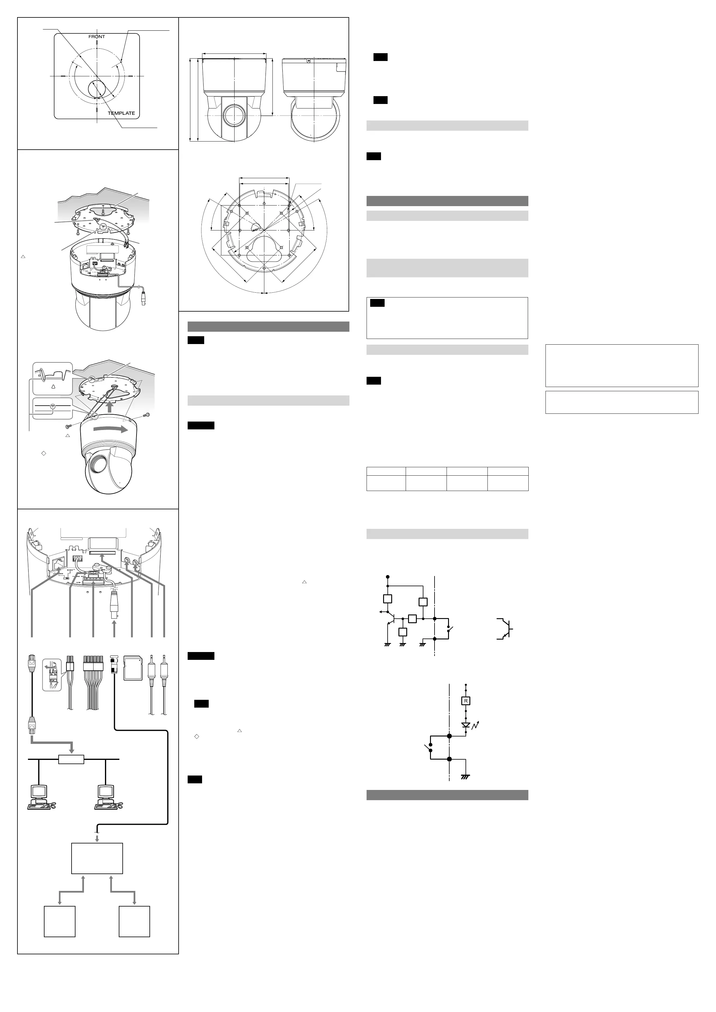
Before installation
Decide the direction in which the camera will shoot, before making holes for
wiring and screw holes.
Push down the perforated tab to bundle the cables from the side of the
camera. (For details, see “ Cable cover” in “Location and Function of Part.”)
Installing directly on a ceiling
Using the supplied template, make a hole for the wiring (ø40 mm (1
5
/
8
inches)).
Determine the location of the three screw holes for attaching the ceiling bracket.
()
Using the existing junction box
Attach the ceiling bracket to the junction box. Screws for this operation are not
supplied.
Attach the ceiling bracket in a manner that the triangular mark faces the front
side of the camera.
Fixing screws
Required screws (not supplied) vary in accordance with the location or material
of the installation.
For steel: Fix with M4 screws and nuts.
For wood: Fix with tapping screws (nominal diameter 4). A material thickness of
15 mm (
19
/
32
inches) or more is necessary.
For a concrete wall: Fix with dry bit or plug bolts.
For a junction box: Fix with screws that accommodate the screw holes in the
junction box.
WARNING
Use the appropriate screws in accordance with the condition and material of the
location site. Otherwise, the ceiling unit may fall and cause serious injury.
How to install
1 Put the built-in wire rope on the hook in the ceiling bracket. (-1)
2 Connect the cables.
Note
Although you can connect the cables while the camera unit is hanging from
the ceiling bracket with the help of the rope, be sure not to put additional
pressure on the unit.
3 Align the triangular mark on the camera with the diamond-shaped
mark on the ceiling bracket, and then attach the camera unit into the
bracket. (-2)
4 Rotate the camera unit in a clockwise direction.
5 Attach the camera unit to the ceiling bracket by fixing two screws at both
sides of the unit.
6 Attach the cable cover.
Note
Use the supplied screws to install the unit. Using other screws may cause
damage inside the unit.
Video S/N 50 dB (Gain 0 dB)
Lens
Focus length SNC-EP580/ER580: f=4.7 to 94.0 mm
SNC-EP550/ER550/ZP550/ZR550: f=3.5 to 98.0
mm
SNC-EP521/EP520/ER521/ER520: f=3.4 to 122.4
mm
Maximum relative aperture SNC-EP580/ER580: F1.6 to F3.5
SNC-EP550/ER550/ZP550/ZR550: F1.35 to F3.7
SNC-EP521/EP520/ER521/ER520: F1.6 to F4.5
Minimum object distance 320 mm
Mechanism
Pan SNC-EP580/EP550/EP521/EP520/ZP550: 340°
SNC-ER580/ER550/ER521/ER520/ZR550: 360°,
endless rotation
Maximum speed: 300°/s
Tilt SNC-EP580/EP550/EP521/EP520/ZP550: 105°
SNC-ER580/ER550/ER521/ER520/ZR550: 210°
(with auto invert function)
Maximum speed: 300°/s
Interface
Network port 10BASE-T/100BASE-TX, auto negotiation (RJ-45)
I/O port Sensor input: × 2, make contact
Alarm output: × 1, 24 V AC/DC, 1 A
(mechanical relay outputs electrically isolated
from the camera)
SD memory card slot
Microphone input Minijack (monaural)
Plug-in-power supported (rated voltage: 2.5 V DC)
Recommended load impedance 2.2 kohms
Line output Minijack (monaural), Maximum output level:
1 Vrms
SLOC port/Monitor output (SNC-ZP550/ZR550)
1.0 Vp-p, 75 ohms, unbalanced, sync negative
(during video output)
Others
Power supply 24 V AC ± 10%, 50 Hz/60 Hz
IEEE802.3at compliant (HPoE system)
Power consumption Max. 25 W
Operating temperature –5°C to +50°C (23°F to 122°F) (activation
temperature range: 0°C to 50°C (32°F to 122°F))
Storage temperature –20°C to +60°C (–4°F to +140°F)
Operating humidity 20% to 80%
Storage humidity 20% to 95%
Dimensions (Diameter/Height)
ø147.4 mm × 190.9 mm (ø5
7
/
8
inches ×
7
5
/
8
inches) (When installing the ceiling bracket,
not including the projecting parts)
Mass Approx. 1.7 kg (3 lb 12 oz) (including ceiling
bracket)
Supplied accessories Ceiling bracket (1)
Screws (2)
Installation manual (1 set)
CD-ROM (User’s Guide, supplied programs) (1)
Template (1)
24 V AC connector (1)
I/O connector (1)
Design and specifications are subject to change without notice.
Recommendation of Periodic Inspections
In case using this device over an extended period of time, please have it
inspected periodically for safe use.
It may appear flawless, but the components may have deteriorated over
time, which may cause a malfunction or accident.
For details, please consult the store of purchase or an authorized Sony dealer.
Adobe and Acrobat Reader are trademarks of Adobe Systems Incorporated in
the United States and/or other countries.
sloc™ is a trademark owned by the Intersil Corporation family of companies.
How to install
1
2
Celing bracket
Camera (When installing the ceiling bracket)
Screw (supplied)
Align the triangular
mark on the camera
with the diamond-
shaped mark on the
ceiling bracket.
Ceiling bracket
Align the triangular
mark with the
front side of the
camera when using
a junction box.
Built-in wire rope
Ceiling
Hook
3-Screw hole
ø130 (5
1
/
8
)
Unit: mm (inches)
ø40 (1
5
/
8
)
Cable hole
120°
120°
85.7 (3
3
/
8
)
83.5 (3
9
/
32
)
Hole 13-ø4.5 (
3
/
16
)
ø130 (5
1
/
8
)
120°
120°
83.5 (3
9
/
32
)
83.5 (3
9
/
32
)
85.7 (3
3
/
8
)
45°
45°
190.9 (7
5
/
8
) (When installing the bracket)
190 (7
1
/
2
) (Camera unit only)
ø147.4 (5
7
/
8
)
132 (5
1
/
4
)
(When installing the bracket)
Unit: mm (inches)
LAN I/O cable24 V AC
Coaxial
cable
Mic
Input
10BASE-T/
100BASE-TX
Hub
Network
Install a hub compatible
with HPoE when using
an HPoE system.
Network cable
(straight, not supplied)
Audio
Output
Ceiling bracket
Ceiling
Unit: mm (inches)
How to remove the camera
1 Loosen and remove the two screws on both sides of the camera unit.
2 Rotate the camera unit in a counterclockwise direction, and remove it
from the ceiling bracket.
3 Disconnect the cables.
Note
Although you can disconnect the cables while the camera unit is hanging
from the ceiling bracket with the help of the rope, be sure not to put
additional pressure on the unit.
4 Unhook the built-in wire rope from the ceiling bracket, and dismount the
camera unit.
Note
Always hold the camera when you dismount the camera unit. This will
prevent any risk of the camera falling.
Install the camera with its head facing upward
Follow the same steps as in “Installing the Camera on a Ceiling” when installing or
removing the camera.
Be sure to place the camera securely to prevent it from falling.
Note
By default, the images from the camera are displayed normally when the camera
is installed on the ceiling. To display the images from the camera in correct way
when you place the camera on the desk top, use the E.flip function.
For the setting of the E.flip function, see the User’s Guide stored in the
supplied CD-ROM.
Connection
Connecting to the Network
Connect the LAN port of the camera unit to a router or hub in the network using
the network cable (straight, not supplied).
To connect to a computer
Connect the LAN port of the camera unit to the network connector of a
computer using the network cable (cross, not supplied).
To connect to a network using a coaxial cable
(SNC-ZP550/ZR550)
When the network connection change switch is set to SLOC, connect to a
network via a coaxial cable.
The maximum coaxial cable length is 3C-2V 300 m.
Note
The high-frequency characteristics of coaxial cables may differ, even if the
cables are of the same classification. Use a high-quality, high-frequency
coaxial cable with this unit.
For details, refer to the instruction manual of the connecting SLOC device.
For further details, please consult an authorized Sony dealer.
Connecting the Power Source
The following two methods are available for connecting to a power source.
24 V AC
HPoE
Note
If you use this camera by feeding power to the LAN port, use the HPoE power
feeding device.
Connecting to a 24 V AC power source supply
Connect the 24 V AC power supply system to the power input terminal of the
camera. The AC power cable is not supplied.
Use a 24 V AC power source isolated commercial power supply.
The usable voltage range is as follows:
24 V AC: 21.6 to 26.4 V
Use a UL cable (VW-1 style 10368) for 24 V AC connection.
Recommended power cable
24 V AC
Cable(AWG)
#24 #22 #20
Maximum cable
length (m (feet))
11 (36.1) 19 (62.3) 28 (91.9)
Connecting to the power supply equipment pursuant to
IEEE802.3at
The power supply equipment pursuant to IEEE802.3at supplies the power
through the LAN cable. For details, refer to the Instruction Manual of the
equipment.
Connecting the I/O Cable
Wiring diagram for sensor input
Mechanical switch/open collector output device
Camera inside
3.3 V
10 kohms
GND
Mechanical
switch
Open collector
output device
Outside
or
2.2 kohms
10 kohms
GNDGND
10 kohms
3 or 1 pin
(Alarm Input 1 or 2)
2 or 4 pin
GND
Wiring diagram for alarm output
Camera inside
5 pin
(Alarm Output +)
Magnet relay
24 V AC
24 V DC,
1 A or less
6 pin
(Alarm Output –)
Outside
24 V DC
Circuit example
GND
Specifications
Compression
Video compression format JPEG/MPEG4/H.264
Audio compression format G.711/G.726 (40,32,24,16 kbps)
Maximum frame rate 30 fps
Camera
Image device SNC-EP580/ER580: 1/2.8 type Exmor CMOS
SNC-EP550/ER550/ZP550/ZR550: 1/4 type Exmor
CMOS
SNC-EP521/EP520/ER521/ER520: 1/4 type
interline transfer CCD
Synchronising Internal
Minimum illumination SNC-EP580/ER580: 1.7 lx (Shutter speed: 1/30 sec,
Exposure: Full auto, 50IRE [IP])
SNC-EP550/ER550/ZP550/ZR550: 1.0 lx (Shutter
speed: 1/60 sec, Exposure: Full auto, 50IRE [IP])
SNC- EP521/ER521: 1.4 lx (Shutter speed: 1/50 sec,
Exposure: Full auto, 50IRE [IP])
SNC- EP520/ER520: 1.4 lx (Shutter speed: 1/60 sec,
Exposure: Full auto, 50IRE [IP])
SD
memory
card
Coaxial cable maximum
length: 3C-2V 300 meters
SLOC connector
SLOC-compatible
device
Video output terminal LAN port (RJ-45)
Coaxial cable
Network cable
10BASE-T/
100BASE-TX
Video monitor (etc.) Network device
 Loading...