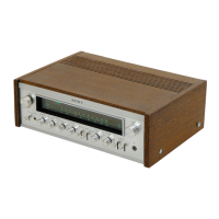
Do you have a question about the Sony STR-7055 and is the answer not in the manual?
| Total Harmonic Distortion | 0.3% |
|---|---|
| Tuning Range | FM, MW |
| Damping Factor | 40 |
| Power Output | 35 watts per channel (8 ohms) |
| Input Sensitivity | 2.5 mV (MM), 250 mV (line) |
| Output | Tape out |
| Speaker Load Impedance | 4 to 16 ohms |
Provides essential safety precautions for handling integrated circuits during servicing.
Details the procedure for safely removing and reinstalling nylon rivets.
Detailed electrical and performance specifications for FM, AM, and audio sections.
Explains the function and operation of key circuits within the receiver.
Illustrates signal voltage levels at various points in the audio path.
Provides a high-level overview of the receiver's internal sections and signal flow.
Instructions for removing the bottom plate of the unit.
Steps for safely removing the front panel assembly.
Procedure for correctly restringing the dial cord mechanism.
Guide for replacing the power output transistors, including heat sink preparation.
Steps to carefully remove the dial glass from the front panel.
Instructions for replacing a defective meter in the unit.
Procedure for replacing the volume control potentiometer.
Guidance for replacing various controls, jacks, and switches.
Diagram showing the internal component arrangement and board locations.
Procedure for aligning the Intermediate Frequency strip in the FM tuner section.
Steps to align the FM discriminator transformer for optimal performance.
Procedure to ensure accurate FM frequency tuning across the band.
Adjusting for maximum stereo separation and minimum distortion.
Steps to adjust the muting circuit threshold for clean reception.
Alignment procedure for the AM tuner's Intermediate Frequency strip.
Aligning AM frequency coverage and ensuring tracking accuracy.
Procedure to calibrate the tuning meter for accurate station indication.
Adjusting the DC bias for the power amplifier output transistors.
Instructions on how to properly repack the unit for shipping or storage.
Shows component placement and connections for the REC/PB connector board.
Illustrates component layout and wiring for the loudness control board.
Component placement and connections for the FM front-end assembly.
Shows component layout and connections for the AM front-end/IF/MPX board.
Provides the detailed circuit schematic for the tuner section.
Illustrates the unit's construction with all parts in an exploded format.
Lists transistors, diodes, FETs, and ICs with part numbers.
Lists transformers, coils, inductors, capacitors, and resistors with part numbers.
Lists switches, filters, connectors, jacks, lamps, and other miscellaneous parts.