STR-DH720/DH720HP
3
TABLE OF CONTENTS
1. SERVICING NOTES
...................................................... 3
2. DISASSEMBLY
2-1. Case ..................................................................................... 5
2-2. D-VIDEO Board ................................................................. 6
2-3. Front Panel Section ............................................................. 6
2-4. Back Panel Section ............................................................. 7
2-5. DIGITAL Board .................................................................. 7
2-6. MAIN Board Section .......................................................... 8
2-7. MAIN Board ....................................................................... 8
3. TEST MODE ..................................................................... 9
4. ELECTRICAL ADJUSTMENT ....................................11
5. DIAGRAMS
5-1. Block Diagram – TUNER/AUDIO Section – ................... 13
5-2. Block Diagram – DIGITAL Section – .............................. 14
5-3. Block Diagram – STANDBY-A VIDEO PC Section–...... 15
5-4. Block Diagram – D-VIDEO Section – ............................. 16
5-5. Block Diagram – KEY/DISPLAY/USB Section – ........... 17
5-6. Block Diagram – POWER KEY Section – ....................... 18
5-7. Printed Wiring Board – DIGITAL Board (Side A) – ........ 20
5-8. Printed Wiring Board – DIGITAL Board (Side B) – ........ 21
5-9. Schematic Diagram – DIGITAL Board (1/4) –................. 22
5-10. Schematic Diagram – DIGITAL Board (2/4) –................. 23
5-11. Schematic Diagram – DIGITAL Board (3/4) –................. 24
5-12. Schematic Diagram – DIGITAL Board (4/4) –................. 25
5-13. Printed Wiring Board – MAIN Board – ............................ 26
5-14. Schematic Diagram – MAIN Board (1/4) – ...................... 27
5-15. Schematic Diagram – MAIN Board (2/4) – ...................... 28
5-16. Schematic Diagram – MAIN Board (3/4) – ...................... 29
5-17. Schematic Diagram – MAIN Board (4/4) – ...................... 30
5-18. Printed Wiring Board – D-VIDEO Board (Side A) – ....... 31
5-19. Printed Wiring Board – D-VIDEO Board (Side B) – ....... 32
5-20. Schematic Diagram – D-VIDEO Board (1/4) – ................ 33
5-21. Schematic Diagram – D-VIDEO Board (2/4) – ................ 34
5-22. Schematic Diagram – D-VIDEO Board (3/4) – ................ 35
5-23. Schematic Diagram – D-VIDEO Board (4/4) – ................ 36
5-24. Printed Wiring Board –
STANDBY-A VIDEO PC Board – ................................... 37
5-25. Schematic Diagram –
STANDBY-A VIDEO PC Board – ................................... 38
5-26. Printed Wiring Boards – PANEL Section – ...................... 39
5-27. Schematic Diagram – PANEL Section – .......................... 40
5-28. Printed Wiring Board – DCDC Board – ........................... 41
5-29. Schematic Diagram – DCDC Board – .............................. 42
5-30. Printed Wiring Board – USB Board – .............................. 43
5-31. Schematic Diagram– USB Board – .................................. 44
5-32. Printed Wiring Board – HEADPHONE Board – .............. 45
5-33. Schematic Diagram – HEADPHONE Board – ................. 45
5-34. Printed Wiring Board – TEMP-SENSOR Board – ........... 45
5-35. Schematic Diagram – TEMP-SENSOR Board – .............. 45
6. EXPLODED VIEWS
6-1. Case Section ...................................................................... 65
6-2. DCDC Board ..................................................................... 66
6-3. Front Panel Section ........................................................... 67
6-4. Back Panel Section ........................................................... 68
6-5. Chassis Section ................................................................. 69
7. ELECTRICAL PARTS LIST ..................................... 70
SECTION 1
SERVICING NOTES
Part No.
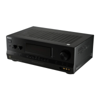
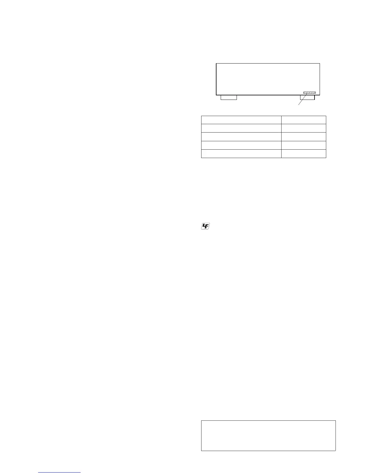
MODEL IDENTIFICATION
–BACK PANEL–
Model Part No.
STR-DH720: US 4-261-825-3
[]
STR-DH720: Canadian 4-261-825-4
[]
STR-DH720: AEP 4-261-825-5
[]
STR-DH720HP: US 4-261-825-7
[]
Notes on chip component replacement
• Never reuse a disconnected chip component.
• Notice that the minus side of a tantalum capacitor may be
damaged by heat.
UNLEADED SOLDER
Boards requiring use of unleaded solder are printed with the
lead-free mark (LF) indicating the solder contains no lead.
(Caution: Some printed circuit boards may not come printed with
the lead free mark due to their particular size)
: LEAD FREE MARK
Unleaded solder has the following characteristics.
• Unleaded solder melts at a temperature about 40 °C higher
than ordinary solder.
Ordinary soldering irons can be used but the iron tip has to be
applied to the solder joint for a slightly longer time.
Soldering irons using a temperature regulator should be set to
about 350 °C.
Caution: The printed pattern (copper foil) may peel away if
the heated tip is applied for too long, so be careful!
• Strong viscosity
Unleaded solder is more viscous (sticky, less prone to fl ow)
than ordinary solder so use caution not to let solder bridges
occur such as on IC pins, etc.
• Usable with ordinary solder
It is best to use only unleaded solder but unleaded solder may
also be added to ordinary solder.
Special Component Notice
The components identified by mark
9
contain confidential
information.
Strictly follow the instructions whenever the components are
repaired and/or replaced.
Notice pour composants spéciaux
Les composants identifiés par la marque
9
contiennent des
informations confi dentielles.
Suivre scrupuleusement les instructions chaque fois qu’un com-
posant est remplacé et / ou réparé.
Note: Refer to supplement-1 for the printed wiring board,
schematic diagram and electrical parts list of D-VIDEO
board (Suffix-21), DIGITAL board (Suffix-21), DCDC
board (Suffi x-21), MAIN board (Suffi x-24) and STANDBY-
AVIDEO MT PC Board (Suffi x-24).
Ver. 1.2
 Loading...