3-6
BVM-D9H1U/D9H5U/D9H1E/D9H5E/D9H1A/D9H5A
Mode
MODE9
MODE13
Signal format
480/60p (525) 4 : 3
480/60i (525) 4 : 3
Screen mode
NORMAL
NORMAL
Mode
MODE23
MODE27
Signal format
575/50p(625) 4 : 3
575/50i(625) 4 : 3
Screen mode
NORMAL
NORMAL
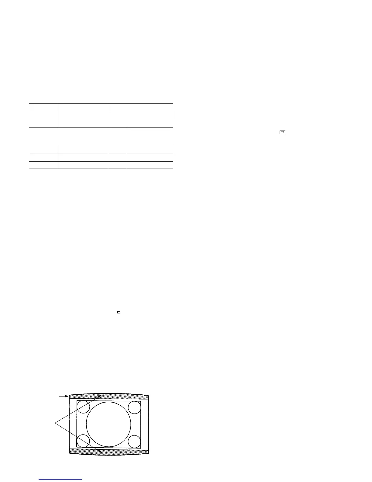
Fig. 1-7
[V. Blanking Adjustment]
..
..
. Preparation
1. Connect the monoscope signal of the signal formats that are
shown in the following table, to the ANALOG Y/G input
connector. Perform the V. blanking adjustment in the
respective screen modes using the respective signal formats.
60 Hz system
50 Hz system
2. Increase the brightness by adjusting the BRIGHT
control so that blanking becomes visible on screen.
Note: The following adjustment menus are located in
the directory under the DEFLECTION menu of the
MAINTENANCE menu.
V BLK TOP
V SIZE
V CENT
..
..
. V. Blanking Adjustment
1. Press the SHIFT button to ON. [The LED (orange) on
top of the button turns on.]
2. Press the 16:9 OFF button [to turn off the LED
(orange)] to select the 4:3 mode.
3. Press the SHIFT button to set the SHIFT OFF. [The
LED (orange) on top of the button turns off.]
4. Press the UNDER SCAN button ( ) to its OFF position to
select the normal mode. [The green LED turns off.]
5
. Adjust the V. SIZE data so that the 5% over-scan is obtained.
6. Take note of the present V. CENT data. After noting,
adjust the V. CENT data so that the top of the raster
becomes visible.
7. Adjust the V. BLK. TOP data so that the vertical
blanking on top of the screen is positioned as closest as
possible to the signal display area.
8. Return the V. CENT data to the original data.
V BLK TOP
V BLK
[Linearity Adjustment]
..
..
. Linearity Adjustment (1)
1. Connect the 1080/60i (1125) cross-hatch signal to the
ANALOG Y/G input connector.
2. Press the SHIFT button to ON. [The LED (orange) on
top of the button turns on.]
3. Press the 16:9 ON button [to turn on the LED (or-
ange)] to select the 16:9 mode.
4. Press the SHIFT button to OFF. [The LED (orange)
on top of the button turns off.]
5. Press the UNDER SCAN button ( ) to its OFF
position to select the normal mode. [The green LED
turns off.]
6. Check that the picture is not slanted, that there are no
top and bottom PIN distortion and horizontal trapezoi-
dal distortion.
Slanted picture :
Adjust inclination of the DY.
Horizontal PIN distortion :
Adjust upper and lower neck twist of the DY.

 Loading...

