FS 120, FS 120 R, FS 250
English
16
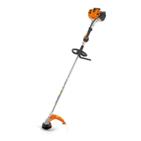
N Place the clamp (3) in the loop
handle (4) and position them both
against the drive tube (5).
N Position the clamp (6) against the
drive tube.
N Place the barrier bar (2) in position
as shown.
N Line up the holes.
N Insert the screws (7) in the holes
and screw them into the barrier
bar (2) as far as stop.
N Go to "Securing the Loop Handle".
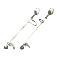
Mounting the Loop Handle without
Barrier Bar
N Place the clamp (3) in the loop
handle (4) and position them both
against the drive tube (5).
N Position the clamp (6) against the
drive tube.
N Line up the holes.
N Fit washers (8) on the screws (7)
and insert the screws in the holes.
Fit the square nuts (1) and screw
them down as far as stop.
N Go to "Securing the Loop Handle".
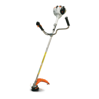
Securing the Loop Handle
The loop handle can be adjusted to suit
the height and reach of the operator and
the application by changing
distance (A).
Recommendation: distance (A):
about 20 cm (8 in)
N Slide the handle to the required
position.
N Line up the loop handle (4).
N Tighten down the screws until the
loop handle can no longer be
rotated on the drive tube. If no
barrier bar is fitted – lock the nuts if
necessary.
The sleeve (9) (not fitted on all models)
must be between the loop handle and
the control handle.
 Loading...