FS 360 C-M, FS 410 C-M, FS 460 C-M, FS 490 C-M
English
16
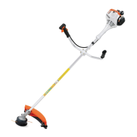
N Position wing screw (8) in threaded
insert in handle support (7) –
against pressure of spring (5).
N Position the clamp moldings so that
the tabs (9) on the lower clamp
molding (6) line up with the
slots (10) in the handle support (7).
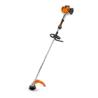
N Rotate wing screw clockwise until
the lower clamp molding (6) butts
against the handle support (7).
N Only tighten the wing screw
moderately.
N Fold the grip of the wing screw down
so that it is flush.
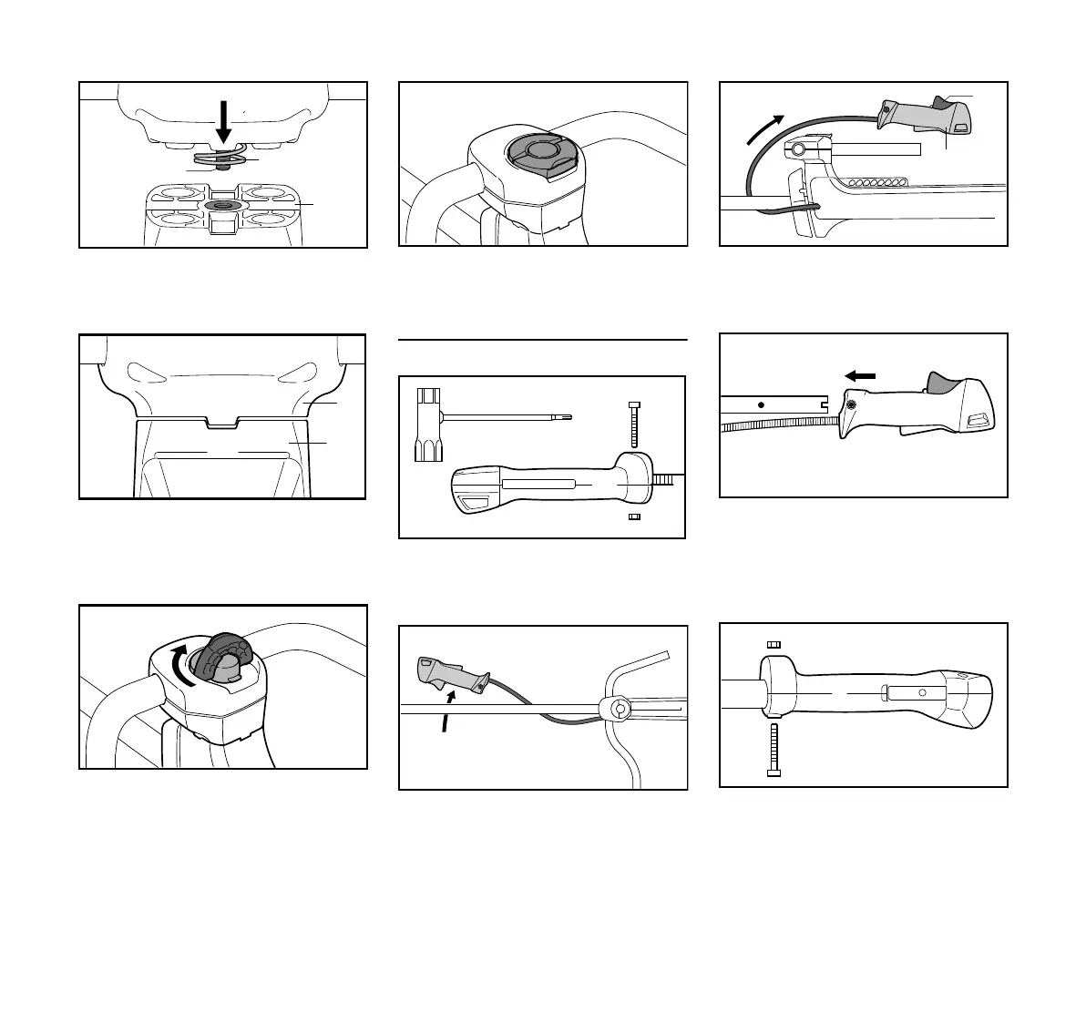
Mounting the Control Handle
N Take out the screw (11) and remove
the nut (12) from the control
handle (1).
N Pass the control handle (1) under
the drive tube and put it down on the
right-hand side of the machine.
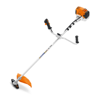
N Swing the control handle (1) behind
the handlebar so that the throttle
trigger (13) is facing up.
N Push the control handle (1) in this
position onto the end of the
handlebar (2) until the holes (14)
are in alignment – the throttle
trigger (13) points up.
N Fit the nut (12) in the control
handle (1), insert the screw (11)
and tighten it down firmly.
 Loading...