Room Probe fail
PP
0 0
> 50 C or <-50 C (when
Probe short circuit, circuit
open or without probe, or
0
temperature is > 50.0 C or
0
<-50.0 C (when rS = 0.1) &
rS = 1)
LP
Keypad lock
Keypad is locked
High temperature alarm
Ht
Low temperature alarm
Lt
Temperature below the
minimum low
temperature limit.
OPERATING MESSAGES
Temperature above the
maximum high
temperature limit.
48
dF
Defrost in progress.
Defrost
LL
Last low temperature
Last low temperature
logged.
LH
Last high temperature
Last high temperature
logged.
rS
In log function: When LL
and LH values are
cleared.
CF
AUX (Auxiliary) Input
Compressor fault
present.
do
Digital input
Door open.
CPP
Coil Probe fail
Probe short circuit, circuit
open or without probe, or
0
temperature is > 50.0 C or
0
<-50.0 C (when rS = 0.1) &
0 0
> 50 C or <-50 C (when
rS = 1)
Password function
" " or " " keys.
Touch & hold " " key for 2sec. Display will flash "P2"
parameter if "PA" value is kept "0". If other than "0", then "PA'
and "0" will flash. Use " "and " " keys to enter the
password. On entering correct value, display will flash the first
parameter "P2". User can scroll through parameters using
In Program mode:
In Set mode:
Touch & hold "SET" key for 2sec. Display will flash set point
value if “PA” parameter value is kept to “0”. If other than “0”,
then display will flash “PA” and “0”. Use " " or " " to enter
the password. On entering correct value, display will flash set
point value. User can set desired value using " "or " "
keys. To save the modified value use "SET" key.
How to reset the Logged values
While the display is showing the logged values, if user
touch & hold the "SET" key for 1sec, the logged values will
be cleared and "rS" will be displayed.
Log Values will get reset after Power ON/OFF.
High and Low temperature logging function
How to see the logged values:
LL : Last Low temperature
LH : Last High temperature
Touch and hold " " key for 1sec. display will flash “LL” and
the corresponding temperature for 4 seconds. After this,
display will flash “LH” and the corresponding temperature for
4 seconds and come out of Log mode and will display
Control probe temperature.
EP Parameter
46
Function: To end programming.
Once the key is pressed, the controller goes
into the normal mode and displays the
temperature and all settings are recorded.
To end
programming
press "SET" key
PA Parameter
43
Min
Max
Fac.
-999
999
-
Function : To change Password.
If password is 0, user can directly access set/program mode.
If the password is kept other then 0, user need to enter correct
password to enter into set/program mode.
User cannot enter into program mode & set mode, if correct
password is not entered.
LP Parameter
44
Min
Max
Fac.
Function: To lock keypad.
When locked all parameters can only be viewed, but not
modified.
Note : If LP parameter is set to and if user tries to change
any parameter value, " LP" will flash on the display.
This parameter is used to lock the keypad so that tampering is
not possible by by-standers.
= keypad locked
= keypad unlocked
Flashing
FS Parameter
45
Function : To restore default settings of the
controller.
When set to 1 all parameters are programmed to factory set
values.
Useful to debug setting related Problems.
2 = FS as per user define
When set to,
0 = FS is disable.
1 = FS as per default value.
Min
Max
Fac.
0
2
-
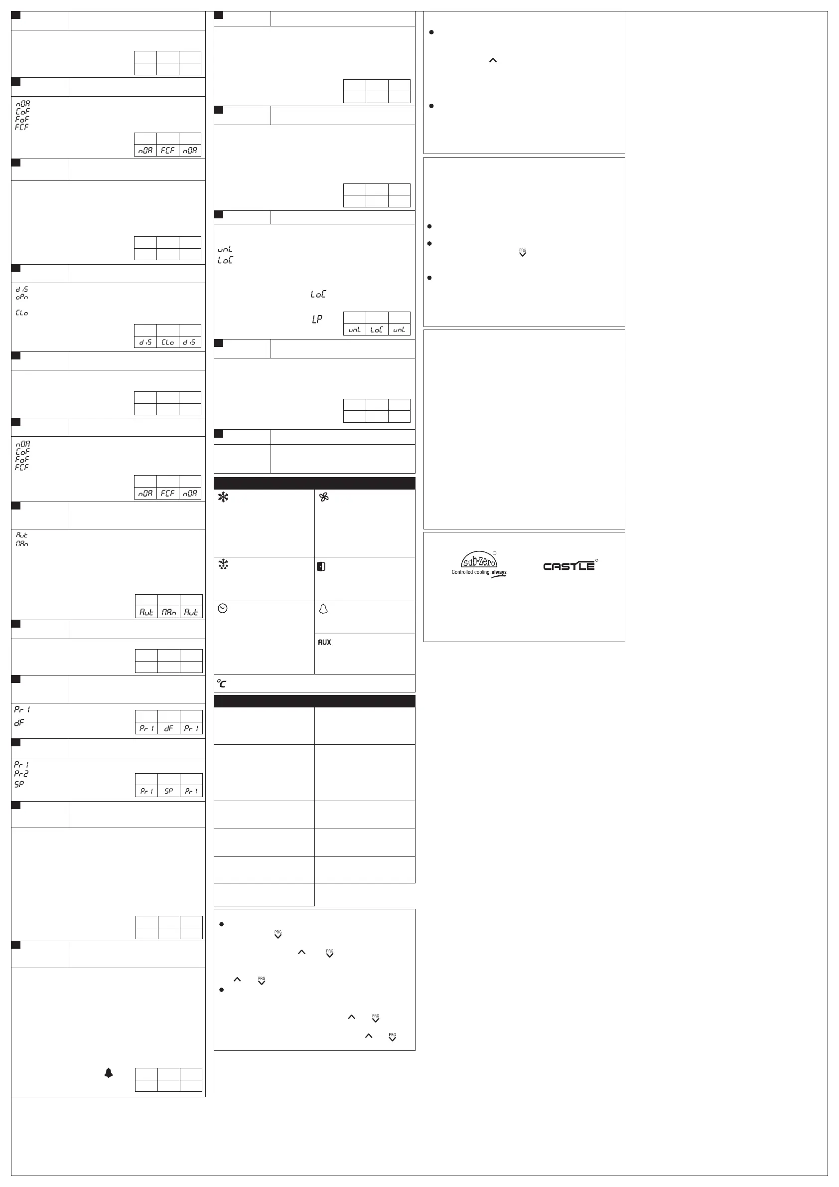
OFF: Compressor is OFF.
ON: Compressor is ON.
Compressor
LEDS
ON: Defrost in progress.
FLASHING :
Drip or post drip
time.
Defrost
47
Fan
Evaporator Fan is in
time delay.
FLASHING:
OFF: Evaporator Fan is
OFF.
ON: Evaporator Fan is
ON.
Time Delay
ON: Compressor is ON
and in time delay
for switching OFF.
(Ot parameter)
FLASHING:
Compressor is in
time delay and
about to start.
ON: Door Open.
Alarm
do, CPP
ON : Ht, Lt, PP, CF,
ON: Auxiliary fault is
present.
ON: When temperature is displayed.
Door Open
User selectable Default values
This can be done by following steps:
User can set their own set of Default Set values for all parameters. If
user wants to activate this feature, Program mode must be accessed
and then change Factory set (FS) parameter accordingly.
Modify values of set point and other parameters as desired by
entering set mode and program mode respectively.
Select FS parameter and touch "SET" key. While display
flashing “0” , touch and hold " " for 10sec. Controller will flash
"-2". Then touch "SET" key. All the user defined parameter
values will be stored as ‘User Default set’.
If user wants to use this set of parameters, access Program
mode and set the FS parameter to "2". Controller will restore the
user defined parameter values.
(Note: Keypad parameter LP and User lock parameter will be
taken into consideration while modifying this parameter.)
Disclaimer: This manual & its contents remain the sole property of
PVR CONTROLS . India and shall not be reproduced or distributed
without authorization. Although great care has been taken in the
preparation of this document, the company or its vendors in no event
will be liable for direct, indirect, special, incidental or consequential
damage arising out of the use or inability to use the product or
documentation, even if advised of the possibility of such damages.
No part of this manual may be reproduced or transmitted in any form
or by any means without the prior written permission of the company.
PVR CONTROLS., reserves the right to make and changes or
improvements without prior notice.
Warranty: This product is warranted against defects in materials and
workmanship for a period of one year from the date of purchase.
During the warranty period, product determined by us to be defective
in form or function will be repaired or, at our option, replaced at no
charge. This warranty does not apply if the product has been
damaged by accident, abuse, and misuse or as a result of service or
modification other than by the company. This warranty is in lieu of any
other warranty expressed or implied. In no event shall the company
be held liable for incidental or consequential damages, including lost
revenue or lost business opportunity arising from the purchase of this
product.
02 / 03.02.2020
Ball Valves
Globe Valves
Hand Valves
Flow Switches
Solenoid Valves
R
Cold Room Controller
Chiller Controller
Two Compressor Controller
Heating Controller
Humidity Controller
Pressure Controller
TM
OUR OTHER PRODUCTS
Min
Max
Fac.
dd Parameter
40
Function : This parameter is used to delay
the display of temperature update by the
set in this parameter.
Each value corresponds to 5 seconds, if the value is set to 1, it
corresponds to 5 seconds, if it is set to 2, it corresponds to 10
seconds and so on.
Min
Max
Fac.
0
36
0
For example, if this parameter is set to 1, temperature on the
display will be updated after 5 seconds. The same value will be
considered for calculation and logging.
Display delay parameter is applicable only when temperature
is increasing (rising). When temperature is decreasing (falling)
this parameter will not be applicable.
If this parameter is set to 0, this feature will be disabled.
CF4
Parameter
37
Function : No of retrials of compressor when
Manual reset is selected.
Min
Max
Fac.
1
10 5
Example : As mentioned in CF3
ddF
Parameter
38
Function : This parameter is used to select
display while the Defrost Cycle is in
progress.
Ad Parameter
41
Function : This parameter is used to set the
time delay at Power ON for Alarm
Indication.
Example: If this parameter is set to 20 minutes, once the
controller is powered ON, no fault indication will be activated
for 20 minutes.
If Control Probe Temperature reaches or drops below P3
parameter value, Low Temperature (Lt) fault will displayed.
If Control Probe Temperature reaches or goes above P2
parameter value, High Temperature (Ht) fault will displayed.
Alarm delay is used only for High Temperature and Low
Temperature, but not for Room Sensor fail.
O
Differential of 1 C is considered for clearing the fault.
Min
Max
Fac.
0 Min
99 Min
20 Min
rS Parameter
42
Function : To set controller resolution.
Note : Temperature and parameter will also change accordingly.
0
This parameter when set to 1,it will take all parameter in 1 C
resolution.
0
This parameter when set to 0.1, it will take all parameter in 0.1 C
resolution.
Min
Max
Fac.
0.1
1
-
nd Parameter
39
Function : Default (Normal) display
= Room Temperature.
= Coil Temperature.
= Set Point
Min
Max
Fac.
Function : To set compressor / fan status
on Compressor fault digital input.
CF2
Parameter
35
Min
Max
Fac.
= Fan will be OFF.
= No action will be performed.
= Compressor will be OFF.
= Fan and Compressor will be OFF.
= Room Temperature
= Defrost Label
CF1
Parameter
34
Min
Max
Fac.
0 sec
99 sec
5 sec
Function : To set compressor fault digital
input sensing delay.
Example : If CF1 = 5seconds and if compressor digital input
(Fault) is present for 5 seconds then fault is detected.
CF3
Parameter
36
Function : To set reset mode for
Compressor output, on Compressor fault
digital input.
= Auto Reset.
= Manual Reset after CF4 retrials in 1 hour.
If this parameter is set to "AUTO" mode then COMP. fault will
be cleared automatically when it is healthy.
Example: If this parameter set to "MAN" mode & CF4 is set
to 5 then, COMP. fault will be cleared after 5 retrials only
after pressing reset key for 2 seconds.
ON
Fault is present
Min
Max
Fac.
CF0
Parameter
33
Function : To activate or deactivate
compressor fault digital input.
= Compressor fault digital input is disabled.
contact is closed.
= Compressor fault digital input is activated when
contact is open.
= Compressor fault digital input is activated when
do3
Parameter
32
Function : To set delay time for temperature
updating at Door open digital input fault.
Min
Max
Fac.
0 sec 180 sec 10 sec
do2
Parameter
31
Min
Max
Fac.
Function : To set compressor / fan status
on Door open fault.
= Compressor will be OFF.
= No action will be performed.
= Fan will be OFF.
= Fan and Compressor will be OFF.
After over the Temperature hold duration display temperature
O
will be increased by 0.1 C at every 1sec until it reaches current
Room Temperature.
Example : This Parameter is set to 60sec, Room Temperature
O
is -18.0 C & Door open condition occurs then Room Temp
O
value -18.0 C at Door open condition will be held for the 60sec
even if Room Temperature is rising.
Min
Max
Fac.
do1
Parameter
30
Min
Max
Fac.
0 sec
99 sec
5 sec
Function : To set door open fault sensing
delay.
Example : If d01 = 5seconds and if digital input (Fault) is
present for 5 seconds then fault is detected.
 Loading...