Suzuki
DT2
WBRICATION
The
power
head
is
lubricated
by o
il
mixed
with
the
fueL Fuel:o
il
ratio
should be
30:1 during
br
ea
k-in
of
a
new
or
rebuilt engine. Fuel:oil ratio for
nor
-
mal service
is
50: I
on
models
prior
to
1987
and
100:1
on
1987
and
later
models. Recommended oil is Suzuki O
ut
-
board Motor
Oil
or
a good quality
NMMA
certified
TC-W
oiL
When using any oth-
er
type
of
two-stroke engine oil, fuel:o
il
ratios should
be
20: I
during
break
-in
and
30:1 for
normal
service
. Manufac-
turer
recommends
regular
or
unleaded
automotive ga';oline having
an
85-95 oc-
tane
rating. Gasoline
and
oil
should
be
thoroughly mixed.
The lower
unit
gears
and
bearings
are
lubricated with SAE 90 hypoid outboard
gear
oil. Lower
unit
capacity
on
models
priorto
1987
is
approximately 40 mL
(1.3
oz.). Oil
capacity
on
lat
er
models
is ap-
proximately
70
mL (2.4 oz.) on
short
drive
shaft
models
and
120 mL
(4
.1 oz.)
on
long drive shaft. models. On
early
models (prior
to
1987). lay
motor
on
side
to
fill
with
oil.
Later
models
are
equipped
with
a
vent
/oil level
check
plug on side
of
gearcase. Reinstall plug
securely using a
new
gasket if necessary
to
ensure
a
water
tight
seal.
FUEL SYSTEM
CARBURETOR. A Mikuni sliding
valve float
type
carburetor
is
used
. Re-
fer to Fig.
S21-1
for
exploded
view. Idle
speed
should
be
adjusted
after
motor
has
reached
normal
operating
temper-
ature. Move speed control to slow
speed
stop
and
adjust idle
speed
screw
(14) to
obtain
idle
speed
of
800-900
rpm.
Note
that
on
1987
and
later
models,
carbure
-
tor
is
equipped
with a pilot
air
screw
(Fig.
SZI-2) for low
speed
mixture
ad-
ju
s
tment.
Carburetor
with
pilot
air
screw
can
be
identified by
the
presence
of
a float bowl drain plug. Initial
setting
of pilot
air
scre
w
is
two
turns
out
from
a lightly
seated
position. Final adjust-
ment
should
be
made
with
engine
at
ope
rating
temperature
and
running
in
forward
gear
. Adjust pilot
air
screw so
engine
idles
smoothly
and
accelerates
without
hesitation.
Main fuel
metering
is controlled by
main
jet
(20-Fig.
SZI-I).
Standard
main
jet
size is
1195
for
models
through
1986
and
1190
for 1987
and
later
models. Nor-
mal position for clip (9)
onjet
needle
(10)
is
third
notch
from
top
of
needle. If
midrange mixture
is
too lean
or
too lich,
minor fuel
mixture
adjustment
can
be
accomplished by
repositioning
clip
on
jet
needle. Moving clip
down
on
needle
richens fuel
mixture
while
moving clip
up
on
needle
leans
fuel
mixture.
Fuel
filter
(17)
should
be
cleaned
after
eve-
ry
50
hours
of
operation.
Th
check float level, remove float bowl
and
invert
carburetor.
With float in-
stalled
on
float
ann
(23), float
surface
nearest
main
jet
should
be
19-21
mm
(0.748-0.826 in.) away from
carburetor
gasket surface. Make
certain
flo
at
is
lev-
el
with
gasket
surface
when
measuring.
Adjust float level by
bending
float
arm
tang.
When installing
carburetor,
renew
"0"
ring (13)
as
required.
IGNITION SYSTEM
Breaker point gap should
be
set
to
0.3-
0.4 mm (0.012-0.016 in.)
at
maximum
opening.
Adjustment
may
be
accom-
plished
through
holes in flywheel. Fly-
wheel
must
be
removed
to
renew
break-
er
ャIッゥョエNセ
N@
Tighten flywheel
nut
to
40-50
N'm (30-37
fUbs
.).
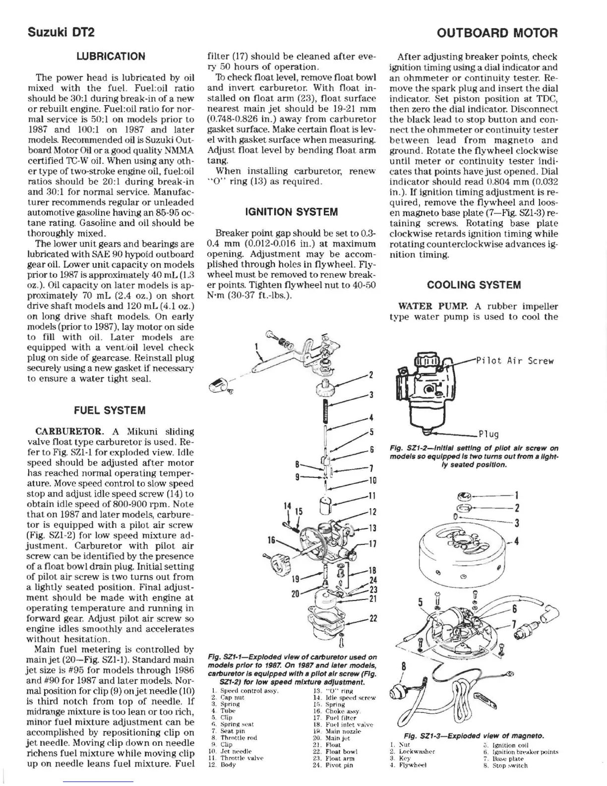
Fig.
SZI-I-Exploded
view
of
c."'urelo,
used on
models
p,'o,
10
1987.
On
1987
snd
I.
Ie'
models,
CB"'urero, Is equipped wlrh • pI/or
.,,
screw (Fig.
SZ1-2)
fo,
'ow
speed
mixture sd/usrmen/.
1.
sーセエNNᄋ、@
co
ntr
ol
a.:;::;y.
13
"0"
イエョセ@
2.
CIlP
nut
14. Idle sp
eed
scrc
.....
3. Spring
tG
. Spring
1. Tube: 16.
c
ィッォ セ@
a..-..,
..
y .
5. C
lip
17
.
FUf'J
(iller
fl
.
SprlnR
!l
C!l(
18
.
l-'uI
.'1
illiN
\.'
;]
\ve
1.
セ。エ@
pin
Qセ
N@
:\11Iin
nO:t:l
lc
8.
Thr
ottle
rod 20.
:\1.'110
j
et
f)
Clip 21.
Float
10 .
.TN
n
..
'OOle
22. Float
bowl
11.
Throttle
valve
23.
FIOfll
ann
12. Dody 2
-1
.
Pi\'ot
pin
OUTBOARD
MOTOR
After
adjusting
breaker
points,
check
ignition timing using a dial indicator
and
an
o
hmmeter
or
continuit.y
tester
.
Re
-
move
the
spark
plug
and
insert
the
dial
indicator.
Set
piston position
at
TOC,
then
zero
the
dial
indicator
. Disconnect
the
black
lead
to
stop
button
and
con-
ne
ct
the
ohmmet.er
or
continuity
tester
between
lead
from
magneto
and
ground.
Rotate
the
flywheel
clockwise
until
meter
or
continuity
tester
indi-
cates
that
points
have
just
opened.
Dial
indicator
should
read
0.804 mm (0.032
in.).
If
ignition timing
adjustment
is re-
quired,
remove
the
flywheel
and
loos-
en
magneto base plate
(7-Fig.
SZI-3) re-
taining
screws. Rotating
base
plate
clockwise
retard
s ignition timing
while
rotating
counterclockwise
advances
ig-
nition
t.iming.
COOLING SYSTEM
WATER PUMP. A
rubb
er impeller
type
water
pump
is
used
to
cool
the
Pilot
Ai
r Screw
.......
--_Plug
Fig.
SZI-2-lnltl.'
setting
of
pilot
.,,
screw
on
models
so
equipped Is
/WO
lums
our from
sllghr-
Iy
seared
position.
---
1
---2
セZNMM]ZZZZZMM
3
Fig.
SZI-3-Exploded
vleMf
of
magnero.
t.
セオイ@
2. Lo('KW3!ihN
3. K(')"
4.
fiyBBィ
セQ@
;).
Ignition coil
6.
iセョゥャ
ゥッ
ョ@
bh'ilk(!r
po
inL"
lJ.a
..
">(!
pl;lle
B. S
top
セキゥエ」ィ@
Download this Manual
 Loading...


