ll brand and product names are trademarks, registered trademarks or service marks of their respective holders.
Installation Manual
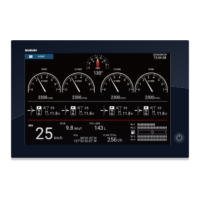
MULTI-FUNCTION DISPLAY
Model SMD12/SMD16
SAFETY INSTRUCTIONS ................................................................................................ i
SYSTEM CONFIGURATION ........................................................................................... ii
EQUIPMENT LISTS........................................................................................................ iii
1. MOUNTING..............................................................................................................1-1
1.1 Mounting Considerations .................................................................................................. 1-1
1.2 Flush Mounting ................................................................................................................. 1-2
1.3 Retrofit Kit for SMD12 (option) and Front Fixing Panel Kit for SMD16 (option) ................ 1-4
1.4 Desktop Mounting (option)................................................................................................ 1-6
1.5 Installation of Transducers................................................................................................ 1-8
1.6 Installation of Sensors (option) ....................................................................................... 1-18
2. WIRING....................................................................................................................2-1
2.1 Interface Connections (Rear of Unit) ................................................................................ 2-1
2.2 How to Secure and Waterproof Connections.................................................................... 2-2
2.3 MULTI Cable..................................................................................................................... 2-2
2.4 DRS Radar Sensor Connections ...................................................................................... 2-6
2.5 Network Connector ........................................................................................................... 2-7
2.6 Video In, Video Out and USB Connections ...................................................................... 2-7
2.7 CAN bus (NMEA2000 Connector) .................................................................................... 2-8
2.8 Example Multi-Function Display System Configurations ................................................ 2-11
3. HOW TO SET UP THE EQUIPMENT......................................................................3-1
3.1 How to Set up the Engine ................................................................................................. 3-4
3.2 SMD Modules ................................................................................................................... 3-8
3.3 Connection Examples of Various Systems ..................................................................... 3-10
3.4 How to Set Time Zone, Time Format and Language...................................................... 3-17
3.5 How to Set Units of Measurement .................................................................................. 3-18
3.6 Initial Setup ..................................................................................................................... 3-19
3.7 How to Set Up the Radar ................................................................................................ 3-25
3.8 How to Set Up the Sounder ............................................................................................ 3-28
3.9 Wireless LAN Setting ...................................................................................................... 3-33
APPENDIX 1 INSTALLATION OF TEMPERATURE SENSORS ............................AP-1
PACKING LISTS ......................................................................................................... A-1
OUTLINES....................................................................................................................D-1
INTERCONNECTION .................................................................................................. S-1

 Loading...