Table Of Contents
COVER
1 Before Repairs
2 Protection Circuitry
3 Accessories
4 Caution for AC Main
Leads
5 Location of Controls
6 Operation Checks and
Component
ReplacementProcedures
6.1 Checking for the AC IN
P.C.B.
6.2 Checking for the
operation P.C.B.
6.3 Checking for the main P.
C.B.
6.4 Replacement for the
regulator transistor
6.5 Replacement for the
power IC
7 To Supply Power Source
8 Self-Diagnostic Mode
8.1 To display the
malfunction code
8.2 To return to the normal
display
8.3 Display contents
8.3.1 U70 CD, U70 DECK
(displayed automatically)
8.3.2 F61
9 Schematic Diagram Notes
10 Schematic Diagram
11 Printed Circuit Board
Diagram
12 Type Illustration of ICs,
Transistors and Diodes
13 Wiring Connection
Diagram
14 Terminal Function of ICs
14.1 IC901
(LC8A524A5N28):System
Control/FL Drive
15 Block Diagram
16 Replacement Parts List
17 Cabinet Parts Location
18 Packaging
Service Manual
TOP NEXT
AD0002043C2
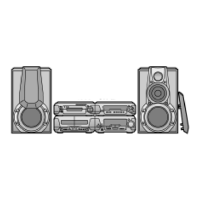
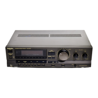
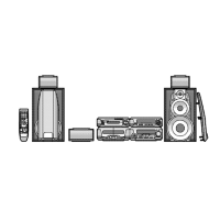
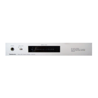
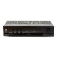
Tuner/Amplifier
SA-EH560
Colour
(S).....................Silver Type
Areas
(E).....................Europe.
(EB)..................Great Britain.
(EG)..................Germany, Italy, France, Netherlands and Denmark.